
Honeycomb structure

A honeycomb structure, honeycomb technology, used in gas treatment, household appliances, engine components, etc., can solve the problems of reduced specific surface area, large thermal stress, uneven heating of exhaust gas, etc., to achieve excellent durability and strong resistance. Effect

Inactive Publication Date: 2006-12-27
IBIDEN CO LTD
View PDF5 Cites 19 Cited by
  • Summary
  • Abstract
  • Description
  • Claims
  • Application Information

AI Technical Summary

Problems solved by technology

[0005] However, the above-mentioned prior art has the following problems: high specific surface area materials such as alumina are sintered due to thermal aging, and the specific surface area decreases; further, with the reduction of specific surface area of ​​high specific surface area materials such as alumina, the burden Catalyst metals such as platinum supported will condense, the particle size will increase, and the specific surface area will decrease
[0013] However, if the thermal expansion coefficient of the honeycomb unit is completely the same as that of the adhesive layer in this way, the obtained honeycomb structure is practically indistinguishable from a honeycomb structure formed of a single ceramic member. When the catalyst is loaded, local temperature changes may occur on the honeycomb structure due to non-uniform catalyst amount, non-uniform heating due to exhaust gas, etc. At this time, there may be a part where the local temperature may change and other parts A large thermal stress is generated between the parts, and cracks are generated on the honeycomb unit or the adhesive layer

Method used


Image

  • Honeycomb structure
  • Honeycomb structure
  • Honeycomb structure

Examples


Embodiment 1

[0156] (1) 40% by weight of γ-alumina particles (average particle size of 2μm) and 10% by weight of silica-alumina fibers (average fiber diameter of 10μm, average fiber length of 100μm, and aspect ratio of 10) , 50% by weight of silica sol (solid concentration of 30% by weight) is mixed to obtain a mixture. With respect to 100 parts by weight of the obtained mixture, 6 parts by weight of methyl cellulose as an organic binder is added, and a small amount of plasticizer and lubricant are added, and further mixing and kneading are performed to obtain a mixed composition. Next, the mixed composition is extruded and molded by an extrusion molding machine to obtain a green body.

[0157] (2) Next, using a microwave dryer and a hot-air dryer, the above-mentioned formed body is sufficiently dried, and further, it is kept at 400° C. for 2 hours for degreasing.

[0158] Then, it was kept at 800°C for 2 hours and fired to obtain a square column shape (34.3mm×34.3mm×150mm) with a cell density...

Embodiment 2、3

[0171] Except having made the honeycomb unit into the shape shown in Table 2, it carried out similarly to Example 1, and manufactured the honeycomb structure.

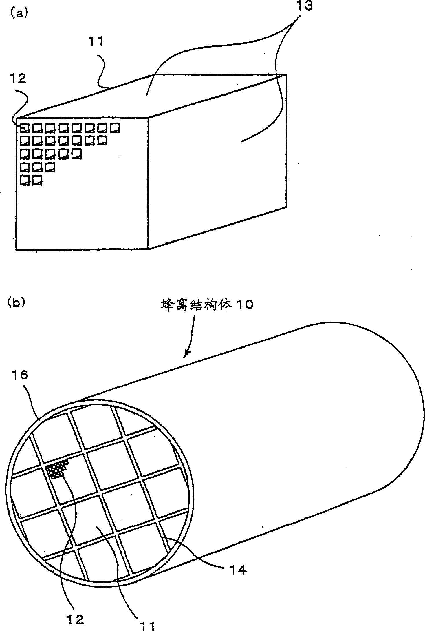
[0172] Moreover, for the ceramic components involved in Examples 2 and 3, the schematic diagrams viewed from the front are as follows: image 3 (b), image 3 (c) Shown.

Embodiment 4

[0174] Except having used the above-mentioned paste B as the sealing material paste and the coating material paste, respectively, it carried out similarly to Example 1, and manufactured the honeycomb structure.


PUM

PropertyMeasurementUnit
areaaaaaaaaaaa
thicknessaaaaaaaaaa
thicknessaaaaaaaaaa

Abstract

A honeycomb structure body where thermal stress caused by a local temperature change in the body can be relaxed, where a crack does not occur, that has high strength and durability, that is resistant to thermal shock and vibration, and where catalyst components can be highly dispersed. The honeycomb structure body is constructed such that column-like honeycomb units are bound together, with seal material layers in between, and the honeycomb units each have a large number of cells arranged side by side, with cell walls in between, so as to be oriented in the longitudinal direction of the units. The honeycomb units contain inorganic particles, and inorganic fibers and / or whiskers, the area of a cross-section of each honeycomb unit orthogonal to the longitudinal direction of each unit is in the range of 5 - 50 cm2, and the thermal expansion coefficient alphaL of the seal material layers and the thermal expansion coefficient alphaF of the honeycomb units satisfy the relationship of 0.01 <= |alphaL-alphaF| / alphaF<= 1.0.

Description

Technical field [0001] The present invention relates to a honeycomb structure. Background technique [0002] In the past, generally, honeycomb catalysts used for exhaust gas purification of automobiles are integrally manufactured by supporting a high specific surface area material such as activated alumina and a catalyst metal such as platinum on the surface of a cordierite honeycomb structure with low thermal expansion properties. In addition, in order to perform NO in an atmosphere with excess oxygen such as lean-burn engines and diesel engines, etc. x Processing, supporting alkaline earth metals such as Ba as NO x Absorbent. [0003] However, in order to further improve the purification performance, it is necessary to improve the exhaust gas and catalyst precious metals and NO x Probability of contact with absorbent. Therefore, it is necessary to further increase the specific surface area of ​​the carrier, reduce the size of the precious metal particles, and make the precious ...

Claims


Application Information

Patent Timeline
Patent Type & Authority Applications(China)
IPC IPC(8): B28D1/00
CPCC04B2111/0081C04B2237/348C04B2237/343C04B2235/5224C04B35/6316Y10T428/24149C04B35/111C04B2237/38C04B35/803C04B2235/5228C04B2111/00198C04B2237/341C04B35/6303C04B41/85B01D2279/30C04B2237/708C04B35/82C04B2111/00793C04B41/508C04B35/6263C04B41/5089C04B2235/526C04B2235/5216C04B2235/5445B01J35/04B01D46/2444B01D46/2429C04B2235/3217B01D46/2448B01D46/2451C04B2237/068C04B2235/5268C04B2237/09C04B2235/5244C04B2237/365C04B2235/522B01D2046/2496C04B2235/5436C04B38/0016C04B41/009C04B2237/34C04B2111/00129C04B2235/3418C04B2237/062C04B2237/064C04B35/18Y10T428/24165C04B2111/2084B01D46/2455C04B37/005C04B2237/346C04B2237/06C04B2235/322C04B35/565B01D46/2459C04B35/14C04B2235/5264C04B2235/5232C04B2235/5296B01J35/002C04B2237/083C04B35/80B01D46/2498B01D46/2484B01D46/24494B01D46/2476B01D46/2478B01J35/30B01J35/56C04B38/0006C04B14/4656C04B41/5031C04B14/4625C04B41/5035C04B41/5059F01N3/022F01N3/02B01D46/2425
Inventor 大野一茂国枝雅文尾久和丈
Owner IBIDEN CO LTD
Learn More