Eureka AIR delivers breakthrough ideas for toughest innovation challenges, trusted by R&D personnel around the world.

Separating method and system for waste paper and waste plastic mixture

A separation system and separation method technology, applied in raw material separation, solid separation, magnetic separation and other directions, can solve the problems of flotation blockage, large water consumption, waste water recontamination, etc., to strengthen rubbing treatment, reduce maintenance costs, reduce The effect of sewage discharge

Inactive Publication Date: 2006-09-20
曾碚凯
View PDF0 Cites 46 Cited by
  • Summary
  • Abstract
  • Description
  • Claims
  • Application Information

AI Technical Summary

Problems solved by technology

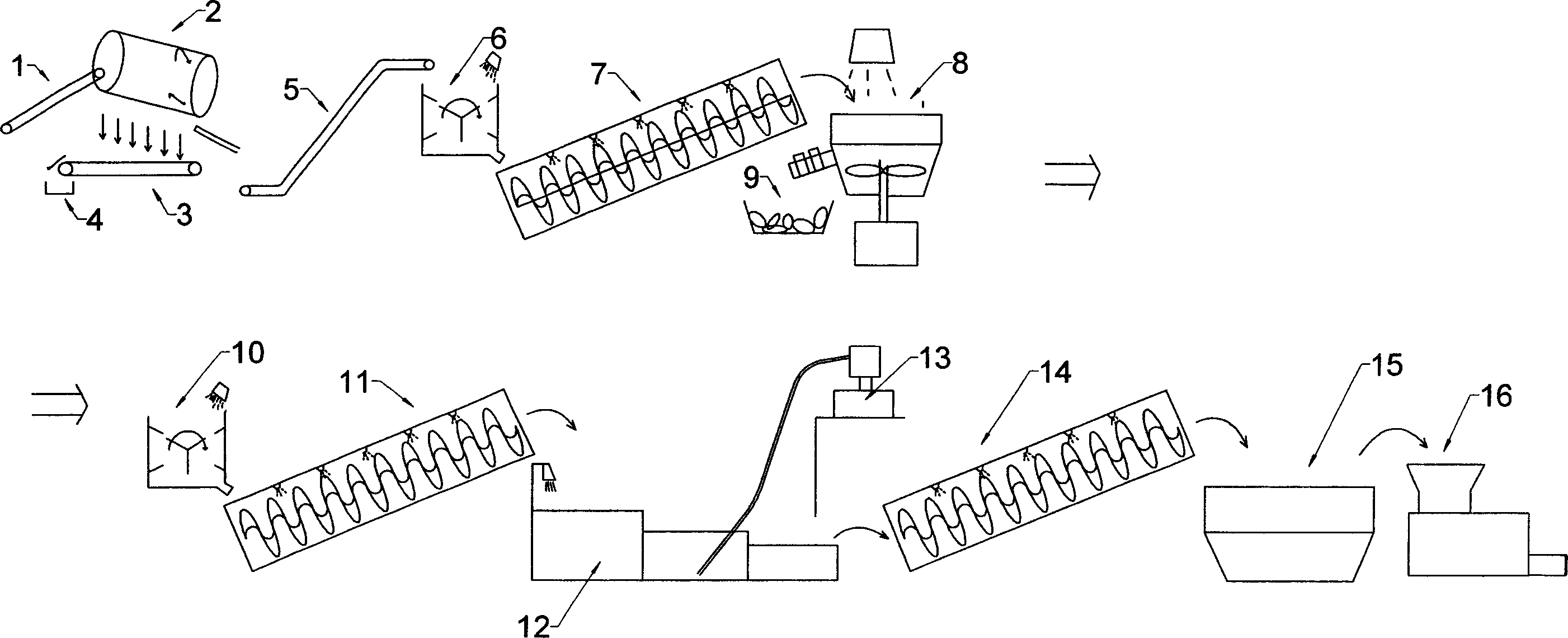
[0005] 1. The primary selection process is too simple and the primary selection efficiency is low, which makes the separation of impurities in the raw materials insufficient, which brings great difficulties to the subsequent flotation treatment
[0006] 2. The water consumption is large, that is, the production water is not recycled during the flotation process of the main working link of the system, resulting in waste of water resources and re-pollution of wastewater
[0007] 3. The coated paper, which is tightly combined with plastic film and paper, is not rubbed sufficiently, so that the paper fiber enters the granulated plastic, which affects the quality of the recycled plastic
[0008] 4. Insufficient flotation, so that a small amount of PVC plastic is mixed with PP, PE, OPP and cannot be separated, so that the latter three will fail to granulate due to the foaming of PVC in the process of heating granulation
[0009] 5. In the flotation, artificially moving suction pipes are used to alternately operate in multiple flotation sub-tanks to suck out the heavy plastic, stone and metal impurities deposited at the bottom of the flotation tank. It is very laborious, the working conditions are bad, and the efficiency is very low.
[0010] 6. Due to the limited water flow of the flotation cell, the floating objects are often blocked on the upstream side of the dividing line of each sub-cell
If a large amount of manual intervention is not carried out, the normal discharge cannot be guaranteed, which seriously affects the production efficiency

Method used


Image

  • Separating method and system for waste paper and waste plastic mixture
  • Separating method and system for waste paper and waste plastic mixture
  • Separating method and system for waste paper and waste plastic mixture

Examples


Embodiment Construction

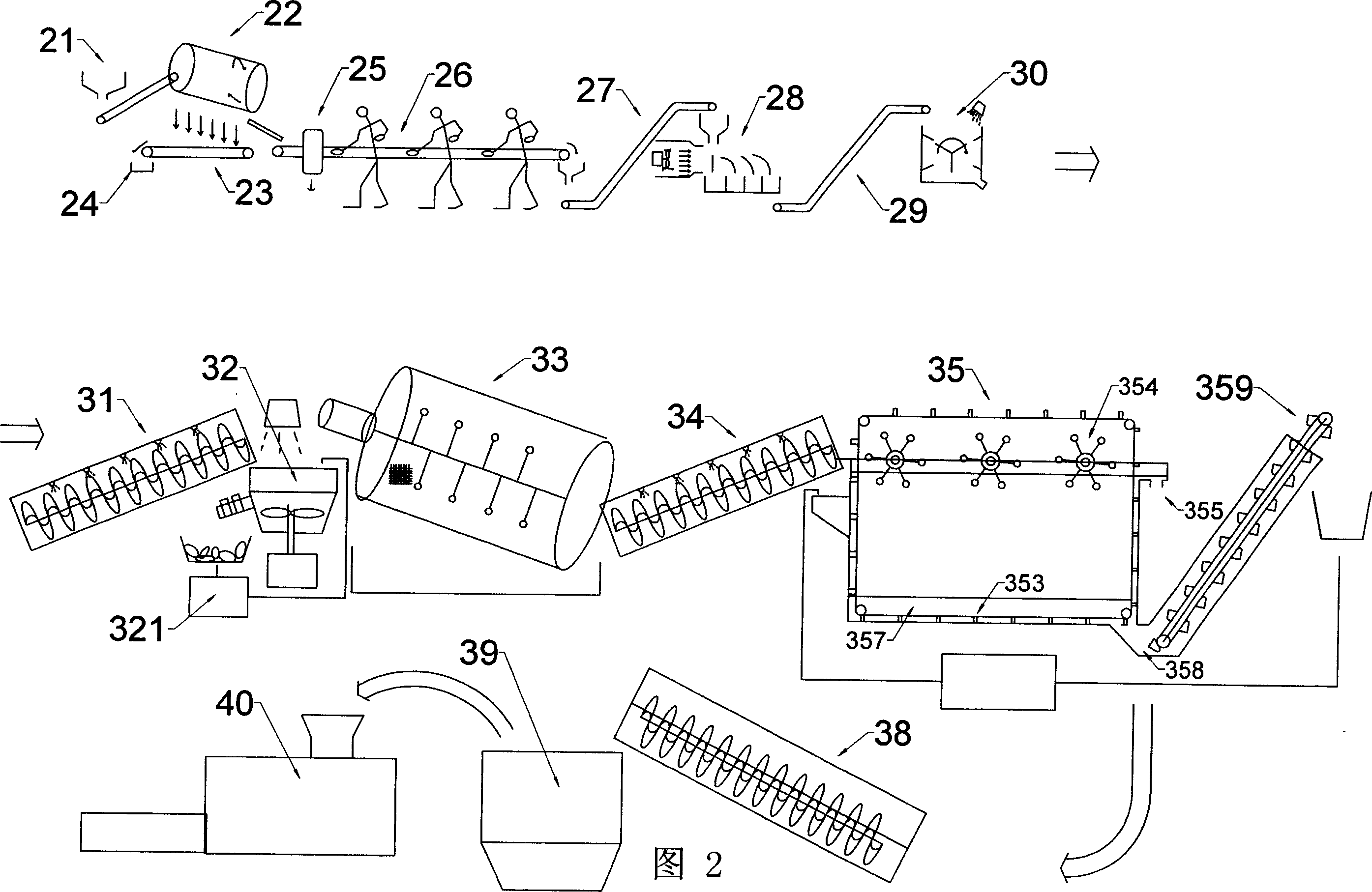
[0045] The present invention will be further described in detail below in conjunction with the accompanying drawings and embodiments.

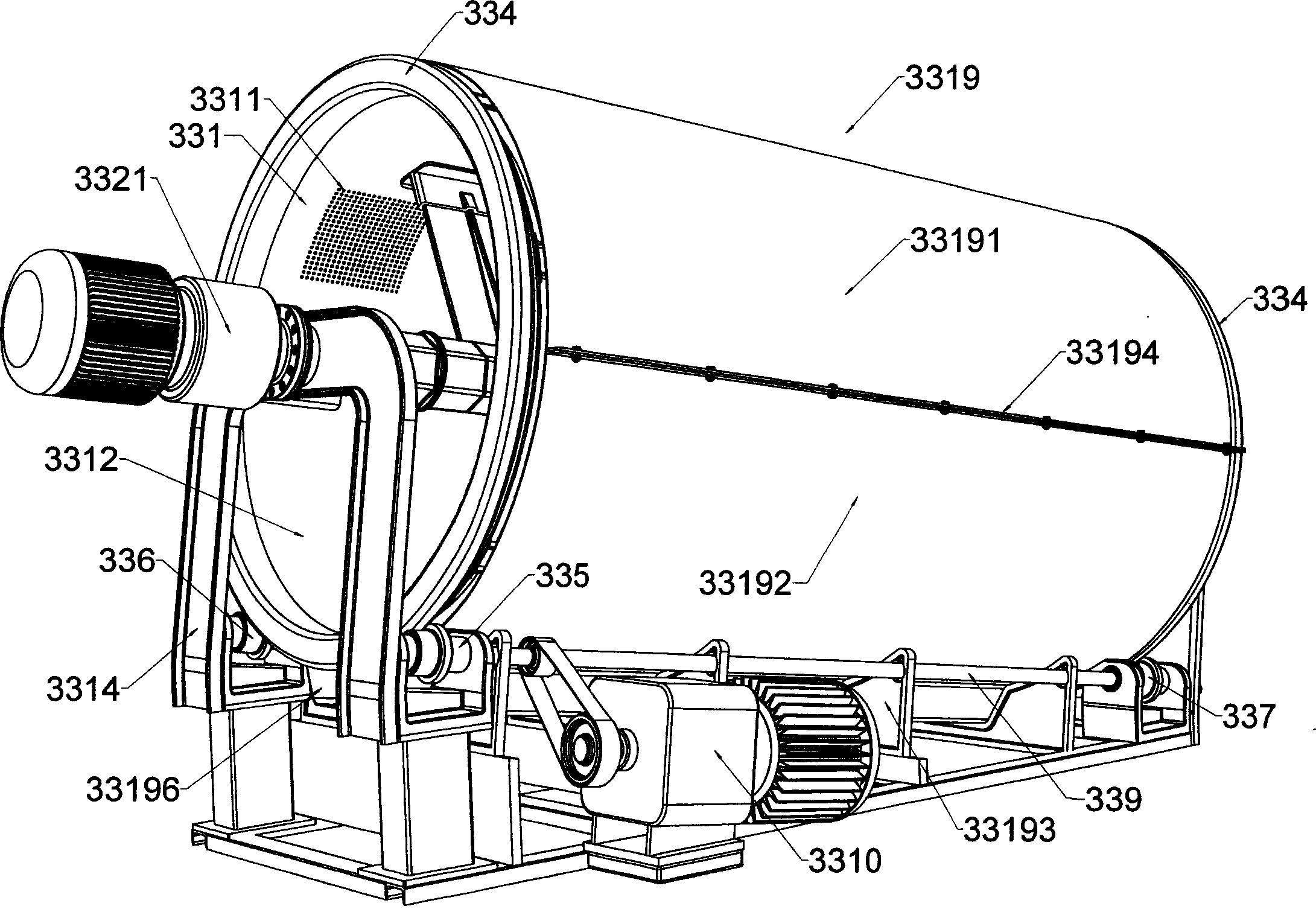
[0046] As shown in Figure 2, the system equipment of the present invention is made up of 14 parts altogether, and they are: quantitative feeding machine 21, trommel B 22, magnetic separation separator 25, manual screening platform 26, winnowing separator 28, pulverizer C30, open separator C31, loose pulp machine B32, rubbing and rolling screen 33, open separator D34, single-stage horizontal flotation cell 35, open separator E38, plastic storage bin 39, granulator 40, among others The connection structure is as follows: the quantitative feeding machine 21 is set at the inlet end of the trommel screen B22, and the magnetic separation separator 25 is arranged at the exit end of the trommel screen B22, and after passing through the manual screening platform 26 and the belt conveyor B27, it reaches the winnowing separator 28, and the pulverizer C30...


PUM


Abstract

A method for separating out waste paper and waste plastic form their mixture including preliminary selecting, using magnetic separator to select out magnetic impurities, using hand to pick up large impurity block without plastic, using fan to blow impurities with different gravities into different grooves at different distance, using mechanical rubbing machine to separate paper fiber from plastic, using single stage floating tank to beat floating matters for releasing paper fiber off, storing floated out plastic and palletizing them for reutilization.

Description

technical field [0001] The invention belongs to the field of papermaking and environmental protection, and relates to pulp waste residue treatment, in particular to a method and system for separating waste paper and waste plastic mixture for extracting plastic from pulp waste in paper mills. Background technique [0002] In modern papermaking raw materials, waste paper occupies a large proportion. my country imported 12.8 million tons of waste paper last year, and it increased at a rate of 36% per year. A considerable amount of waste paper is composite materials of paper and plastics. . In the process of separating raw materials, paper mills will separate this part of the material, which accounts for about 5% of the waste paper. Because the paper fiber and plastic of this part of the material are very tightly combined, it cannot be separated by ordinary separation technology, so this part It cannot be reused by paper mills and becomes pulp waste. The traditional method is t...

Claims


Application Information

Patent Timeline
IPC IPC(8): D21B1/30D21B1/02D21C9/02B03C1/00B07B7/00B03D1/00
Inventor 曾碚凯傅祖鸿曾碚勇
Owner 曾碚凯
Why Eureka
Eureka Blog
Learn More