
Endless belt for image-forming apparatuses, and image-forming apparatus

An endless belt and image technology, which is applied to the electrical recording process using the charge pattern, equipment and instruments for the electric recording process using the charge pattern, and can solve the problem of large inhomogeneity of resistivity and poor release of toner , Toner transfer efficiency is easy to deteriorate, etc., to achieve the effect of excellent bending resistance or chemical resistance, excellent molding dimensional stability, and excellent external environment stability

Inactive Publication Date: 2006-08-30
MITSUBISHI RAYON CO LTD +1
View PDF13 Cites 7 Cited by
  • Summary
  • Abstract
  • Description
  • Claims
  • Application Information

AI Technical Summary

Problems solved by technology

[0041] In ribbons alloyed with thermoplastic resin and thermoplastic elastomer (Patent Documents 6 and 7), since the dispersibility of thermoplastic resin and thermoplastic elastomer is poor, carbon is easily aggregated, and therefore, there is a large dependence of resistance value on voltage, and resistance Tendency to increase the unevenness of the rate
In addition, there is a problem that the voltage dependence of resistivity and the change of resistivity due to temperature and humidity also become large, and high-precision image quality cannot be obtained under all conditions of use.
In addition, when installed in an image forming apparatus, there is also a problem of leakage resistance of the annular belt due to application of high voltage
[0042] A tape obtained by alloying a thermoplastic resin and a low-melting-point thermoplastic elastomer (Patent Document 8) has a problem of image shift because the tape is easily stretched by using a low-melting-point thermoplastic elastomer.
In addition, since the releasability of the toner in the soft segment portion of the thermoplastic elastomer is poor, there is a problem that the transfer efficiency of the toner from the belt to the secondary transfer portion of the paper tends to deteriorate.
In addition, when the extrusion molding method is used, it is difficult to make the endless belt into a perfect circle due to its high flexibility, and there is a problem that post-processes such as heat treatment are necessary.
In addition, since there are few crystalline components, the chemical resistance is poor, and there is also a problem of deterioration due to the influence of silicone oil, etc. generated from the fixing member, etc.
[0043] A tape with reduced elongation and flexibility (Patent Document 9) obtained by extrusion molding a laminated tape of a thermoplastic resin and a thermoplastic elastomer has mutual influence due to disturbance of the flow characteristics of various molten resins during molding. The resistance of the layer has an influence, so there is a problem of uneven resistance value of the band
In addition, since the surface layer is a thermoplastic elastomer, there are few crystalline components, poor chemical resistance, and there is a problem of deterioration due to the influence of silicone oil, etc. generated from the fixing member, etc.

Method used

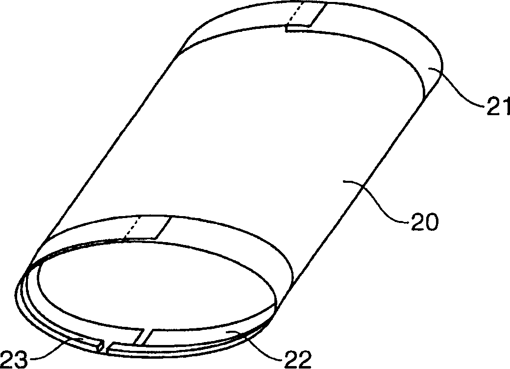
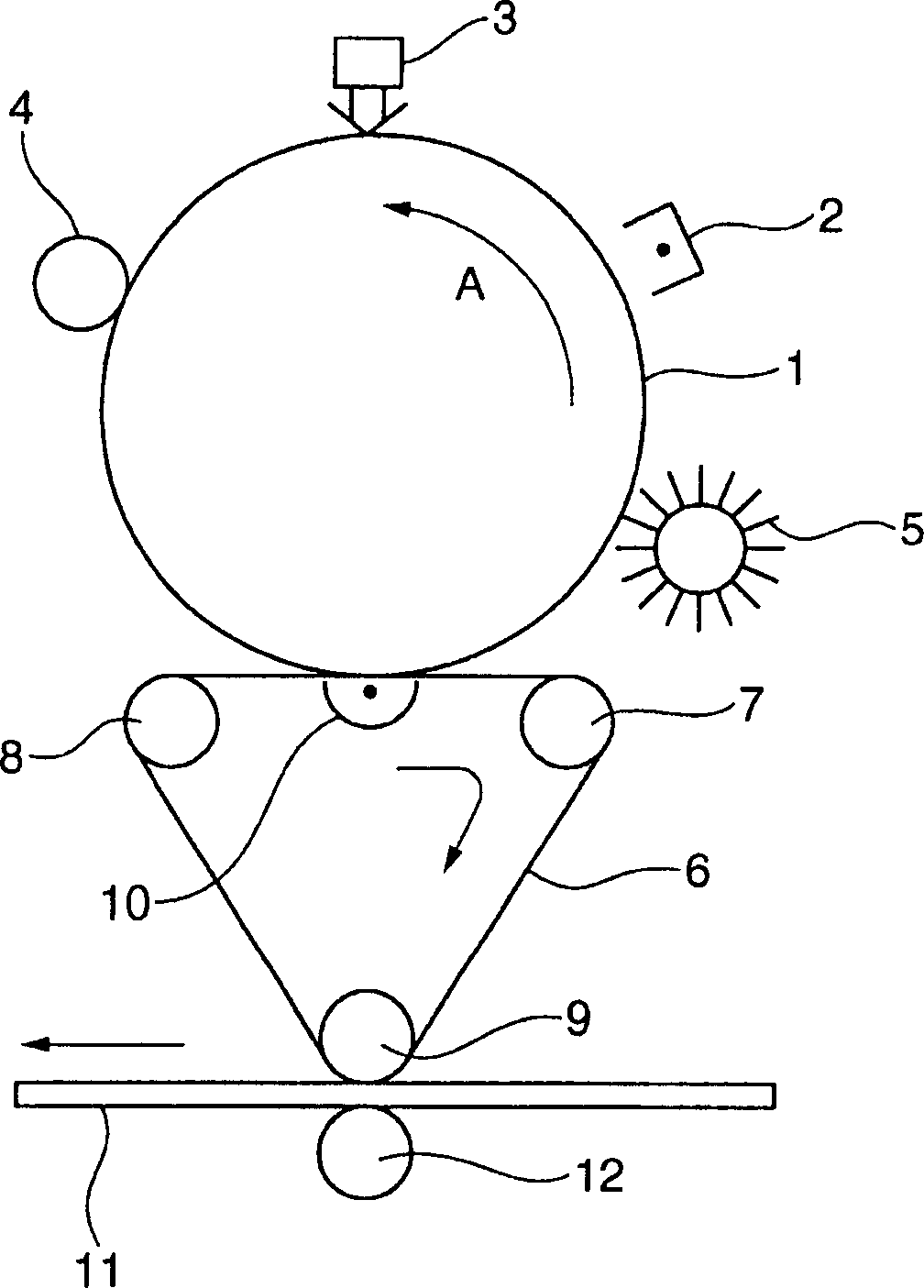
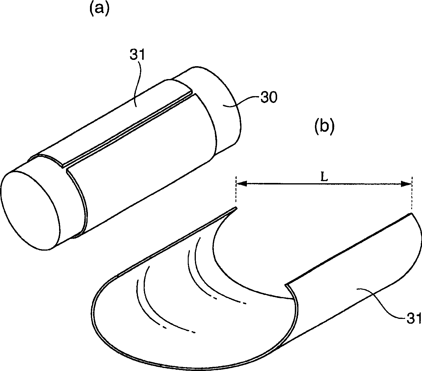

Image

  • Endless belt for image-forming apparatuses, and image-forming apparatus
  • Endless belt for image-forming apparatuses, and image-forming apparatus
  • Endless belt for image-forming apparatuses, and image-forming apparatus

Examples


Embodiment 1~8、 comparative example 1~4

[0417]

[0418] These examples are examples for explaining the invention of the first point, the second point, and the fourth point.

Embodiment 1~4

[0420] Heating is carried out with the ratio described in Table 1 to obtain material particles. At this time, the heating kneading conditions are shown in Table 1, the resin temperature is adjusted, and the retention time in the kneading machine is adjusted, and the kneading conditions are adjusted to suppress the reaction inhibition in the kneader while the resistance is a semiconductive region. Extruded molded material particles, manufacturing the ring belt. Further, in Table 1, the amount of carbon black, chelating agent, and the tackifier in combined * is 100 parts by weight of the total amount of 100 parts by weight relative to the thermoplastic elastomer and the thermoplastic resin.

[0421] Any kind of ring belt, surface resistivity SR (100V) average is 1 × 10 11 ~ 2 × 10 11 Ω / □, the volume resistivity VR (100V) average is 3.6 × 10 10 ~ 6.0 × 10 1 0 Ω · cm, the voltage dependent SR (100V) / SR (500V) of the surface resistivity is 1.5 ~ 5, within 1 order level (10 times), ...

Embodiment 5

[0425] In addition to changing the type of the thermoplastic elastomer, the annular belt is obtained in the same manner as in Example 1. Example 5 can also be excellent in appearance and a ring strip which is less resistant to a low resistivity due to a low resistance rate change and a small resistance rate due to a low resistance rate. When the ring belt is mounted in the image forming apparatus, a good image can be obtained. The main manufacturing conditions and various characteristics at this time are shown in Tables 1 and 2.


PUM

PropertyMeasurementUnit
Surface resistivityaaaaaaaaaa
Volume resistivityaaaaaaaaaa
Crystal melting pointaaaaaaaaaa

Abstract

An endless belt for image forming devices is disclosed. The endless belt is produced by molding a compound comprising a thermoplastic elastomer, a thermoplastic resin, and a conductive material, and satisfies formulae (1), (2), (3) shown below. An image forming device using this endless belt is also disclosed. [FORMULAE 1] SR(100V) / SR(500V) G03G 15 / 16 G03G 15 / 08 G03G 15 / 20 G03G 21 / 00 G03G 5 / 10 6 53 4 2004 / 7 / 23 1826561 2006 / 8 / 30 100444042 2008 / 12 / 17 2008 / 12 / 17 2008 / 12 / 17 Mitsubishi Chem Corp. Japan Morikoshi Makoto Otsu Toshihiro Yamaoka Katsushi Mizumoto Kazuya zhang bengyuan zhao renlin 11105 Japan 2003 / 7 / 25 201844 / 2003 Japan 2003 / 9 / 5 314291 / 2003 Japan 2004 / 4 / 12 116996 / 2004 Japan 2004 / 4 / 23 128485 / 2004 2006 / 1 / 23 PCT / JP2004 / 010458 2004 / 7 / 23 WO2005 / 010621 2005 / 2 / 3 Japanese

Description

Technical field [0001] The present invention relates to an endless belt for an image forming apparatus and an image forming apparatus. In particular, it relates to an endless belt for an endless (loop) image forming apparatus having excellent physical properties such as molding dimensional stability and bending resistance, and an image having the endless belt Forming device. The endless belt of the present invention is suitable as an intermediate transfer belt, a conveying transfer belt, a photoreceptor belt, a fixing belt, and other image forming apparatus belts used in electrophotographic copying machines, laser printers, LED printers, facsimile machines, and the like. Background technique [0002] In the past, as image forming devices such as OA equipment, electrophotographic methods using photoreceptors and toners were designed and marketed. In these devices, regardless of whether there is a joint, a photoreceptor belt, an intermediate transfer belt, a conveying transfer belt...

Claims


Application Information

Patent Timeline
IPC IPC(8): G03G15/16G03G15/08G03G15/20G03G21/00G03G5/10
Inventor 森越诚大津纪宏山冈克史水本和也
Owner MITSUBISHI RAYON CO LTD
Learn More