Dual positive clearance blanking method
A gap and dual technology, applied in the field of stamping process separation processing, can solve the problem of not finding a higher shear surface
- Summary
- Abstract
- Description
- Claims
- Application Information
AI Technical Summary
Problems solved by technology
Method used
Image
Examples
Embodiment 1
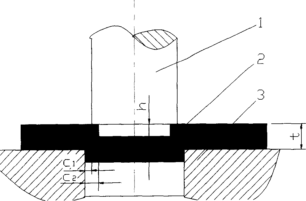
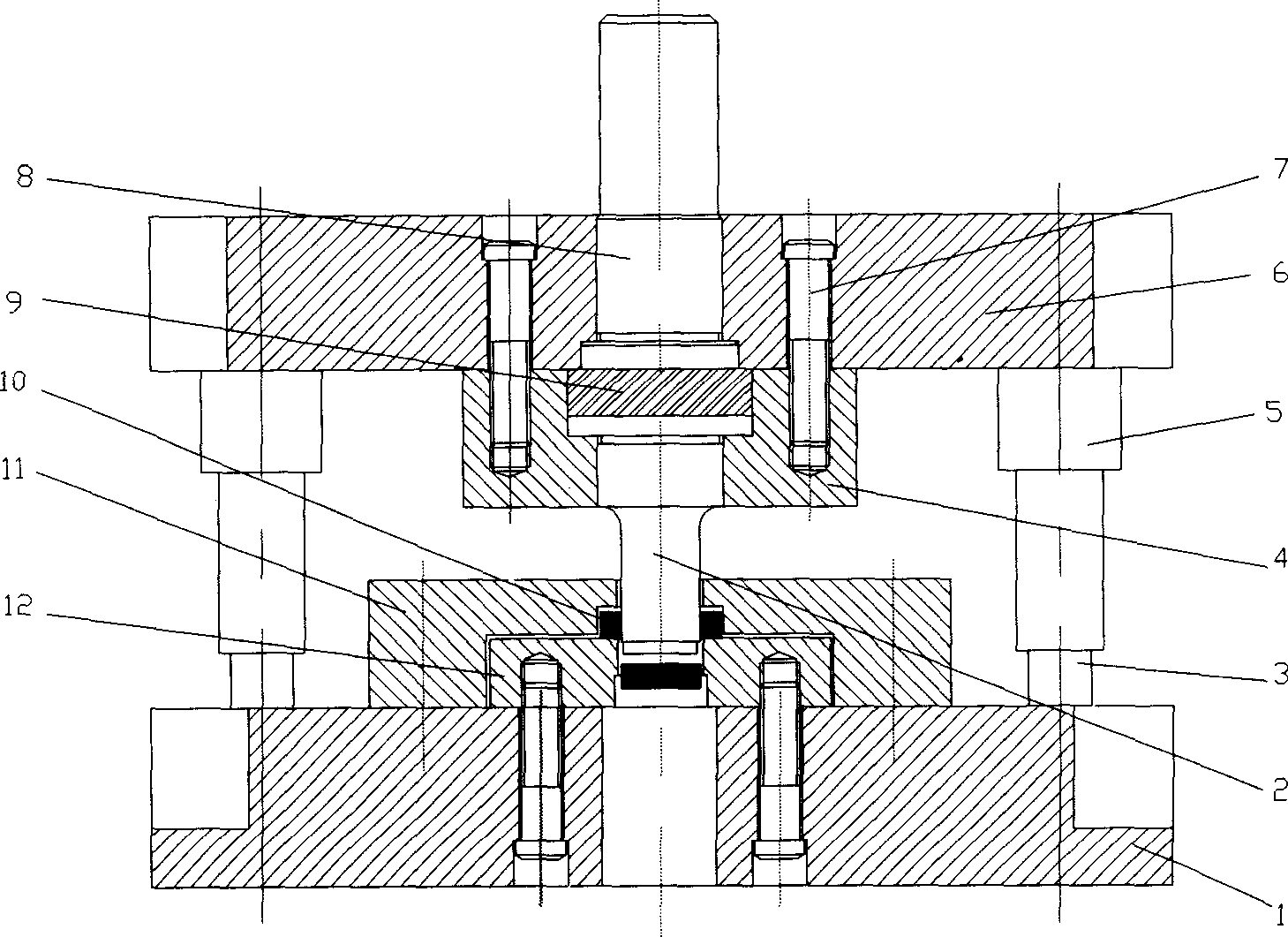
[0024] This embodiment is punching in the method of the present invention, that is, to make a continuous step-shaped punch to form double positive gaps (C1 and C2) between it and the die, and attach figure 1 It is the punching schematic diagram of this embodiment, with Figure 5 It is a schematic diagram of the punching section of this embodiment. Present embodiment is to use two kinds of materials that thickness is 4mm, implements on 100KN ordinary press, and workpiece diameter is φ 20mm. The process conditions and results are shown in Table 1.
[0025] serial number
[0026] For ordinary blanking under the same blanking conditions (material, material thickness, press), when C is 0.1t, the height of the shear surface of the pure aluminum plate is less than 1.5mm, and the height of the shear surface of the brass plate is less than 1.0mm.
Embodiment 2
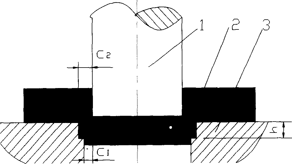
[0028] This embodiment is blanking in the method of the present invention, that is, to make a continuous step-shaped die to form double positive gaps (C1 and C2) between it and the punch, and attach figure 2 It is the blanking schematic diagram of this embodiment, with Figure 5 It is a schematic diagram of the punching section of this embodiment. Present embodiment is to use two kinds of materials that thickness is 4mm, implements on 100KN ordinary press, and workpiece diameter is φ 20mm. The process conditions and results are shown in Table 2.
[0029] serial number
[0030] For ordinary blanking under the same blanking conditions (material, material thickness, press), when C is 0.1t, the height of the shear surface of the pure aluminum plate is less than 1.5mm, and the height of the shear surface of the brass plate is less than 1.0mm.
Embodiment 3
[0032] This embodiment is punching in the method of the present invention, that is, to make a continuous step-shaped punch to form double positive gaps (C1 and C2) between it and the die, and attach figure 1 It is the punching schematic diagram of this embodiment, with Figure 5 It is a schematic diagram of the punching section of this embodiment. Present embodiment is to use two kinds of materials that thickness is 6mm, implements on 250KN ordinary press, and workpiece diameter is φ 20mm. The process conditions and results are shown in Table 3.
[0033] serial number
[0034] For ordinary punching under the same blanking conditions (material, material thickness, press), when C is 0.1t, the height of the shear surface of the pure aluminum plate is less than 2.5mm, and the height of the shear surface of the brass plate is less than 1.5mm.
PUM
 Abstract
Description
Claims
Application Information
 - R&D
- Intellectual Property
- Life Sciences
- Materials
- Tech Scout
- Unparalleled Data Quality
- Higher Quality Content
- 60% Fewer Hallucinations
Browse by: Latest US Patents, China's latest patents, Technical Efficacy Thesaurus, Application Domain, Technology Topic, Popular Technical Reports.
© 2025 PatSnap. All rights reserved.Legal|Privacy policy|Modern Slavery Act Transparency Statement|Sitemap|About US| Contact US: help@patsnap.com


