


Quick Research
Generate reliable direction feasibility study reports for your R&D in just a few steps.

Technical Q&A
Discover and master advanced knowledge NOW. Basics, ideas, possibilities, all at once.

Find Solutions
As an expert in R&D theories, this can generate solutions to your technical problems instantly.

Evaluate Feasibility
Analyze your overall solution with one click, know your potential R&D risks in advance.

Monitor Landscape
Get weekly tech updates, stay abreast of the latest tech innovations and key insights.
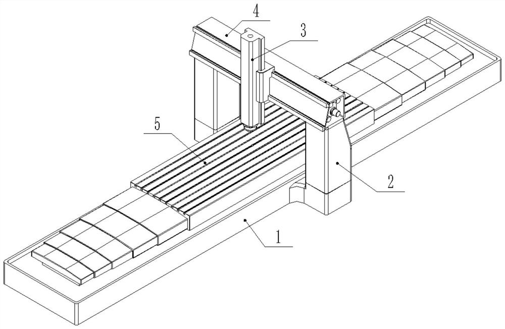
Self-straightening machine tool cross beam
A beam and machine tool technology, applied in the field of self-aligning machine tool beams, can solve the problems affecting the overall rigidity of the machine tool frame, reducing the machining accuracy of the machine tool, and deforming the machine tool beam, so as to improve rigidity, increase manufacturing difficulty, and improve rigidity and stability. Effect
- Summary
- Abstract
- Description
- Claims
- Application Information
AI Technical Summary
Problems solved by technology
Method used
Image

Examples
Embodiment Construction
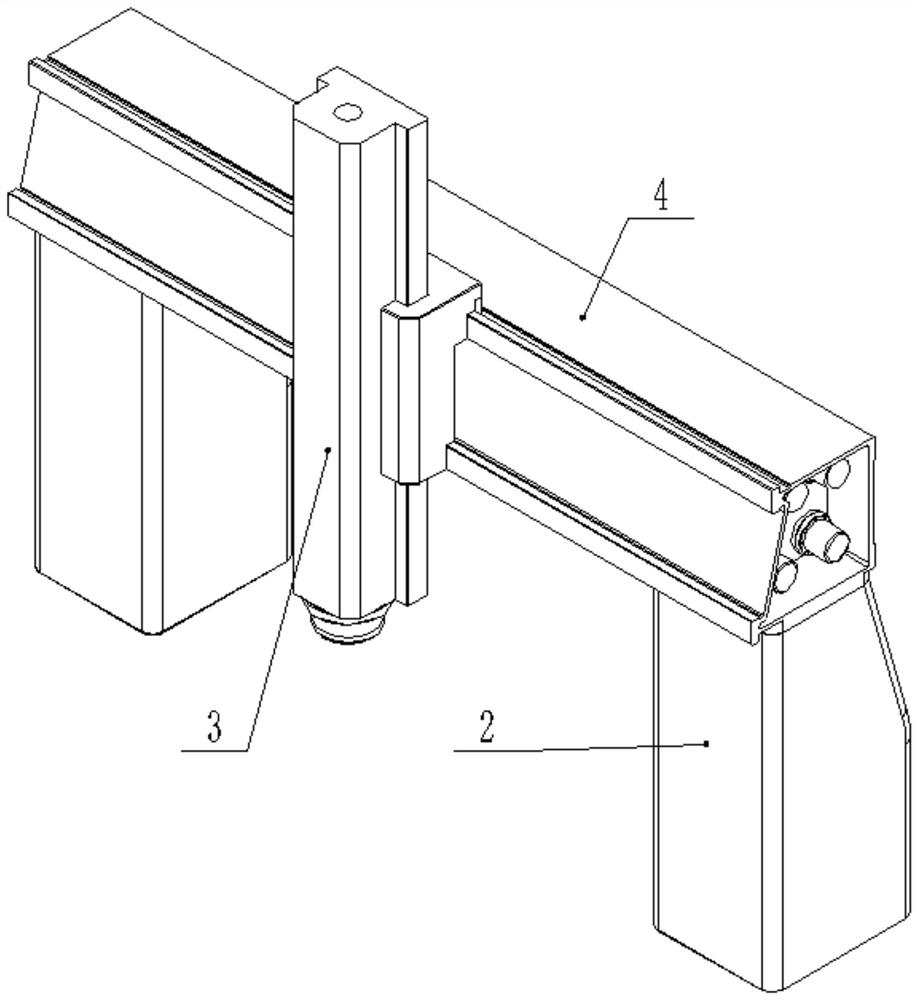
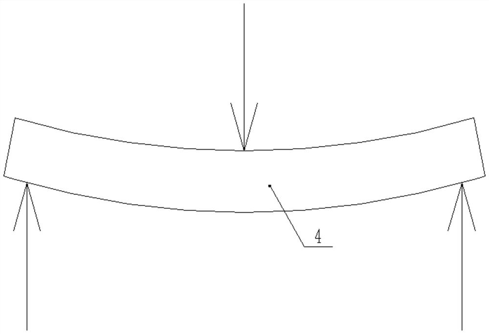
[0032] A self-straightening machine tool beam provided by an embodiment of the present invention, such as Figure 2 to Figure 11 As shown, the self-aligning machine beam provided by the embodiment of the present invention includes a beam body 401 , several tie bars 402 , a tension device, a sensor 405 , a washer 406 and a nut 407 . Such as figure 2 , Figure 7 , Figure 8 As shown, the beam body 401 and figure 2 The column 2 in the middle is connected, and the beam body 401 is a barrel-shaped structure with both ends closed, and its cross section (the cross section perpendicular to the length direction of the beam is a cross section) is rectangular or trapezoidal, and the horizontal direction of the abdominal cavity of the beam body 401 is provided with longitudinal ribs 4011, the longitudinal rib 4011 is placed in the middle of the beam body 401, and the longitudinal rib 4011 is fixedly connected to the two ends of the beam body 401. The longitudinal ribs 4011 directly ...
PUM
 Abstract
Description
Claims
Application Information
 - R&D Engineer
- R&D Manager
- IP Professional
- Industry Leading Data Capabilities
- Powerful AI technology
- Patent DNA Extraction
Browse by: Latest US Patents, China's latest patents, Technical Efficacy Thesaurus, Application Domain, Technology Topic, Popular Technical Reports.
© 2024 PatSnap. All rights reserved.Legal|Privacy policy|Modern Slavery Act Transparency Statement|Sitemap|About US| Contact US: help@patsnap.com