A self-aligning machine tool beam

A beam and machine tool technology, applied in metal processing mechanical parts, metal processing equipment, manufacturing tools, etc., can solve the problems affecting the overall stiffness of the machine frame, the reduction of the machining accuracy of the machine tool, and the deformation of the machine tool beam, so as to improve the stiffness and manufacturing difficulty. The effect of increased, rigidity and stability improvement

Active Publication Date: 2022-07-05
SHANDONG MACHINERY DESIGN INST
View PDF0 Cites 0 Cited by
  • Summary
  • Abstract
  • Description
  • Claims
  • Application Information

AI Technical Summary

Problems solved by technology

In practice, the deformation of the beam is not only affected by the pressure of the slide plate ram spindle head assembly 3, but also affected by many factors such as instantaneous cutting resistance, friction, vibration and temperature. The deformation and poor rigidity of the machine tool beam will not only affect the machine tool. The overall rigidity of the frame, and the deformation of the beam will directly lead to the reduction of the machining accuracy of the machine tool. Therefore, in the research of continuously improving the precision and stability of high-end CNC machine tools, how to improve the rigidity and stability of the machine tool beam is the current research of the machine tool industry. Key topics, that is to say, if the rigidity and stability of the beam of the machine tool are improved, the precision and stability of the high-end CNC machine tool can also be improved

Method used


Image

  • A self-aligning machine tool beam
  • A self-aligning machine tool beam
  • A self-aligning machine tool beam

Examples


Embodiment Construction

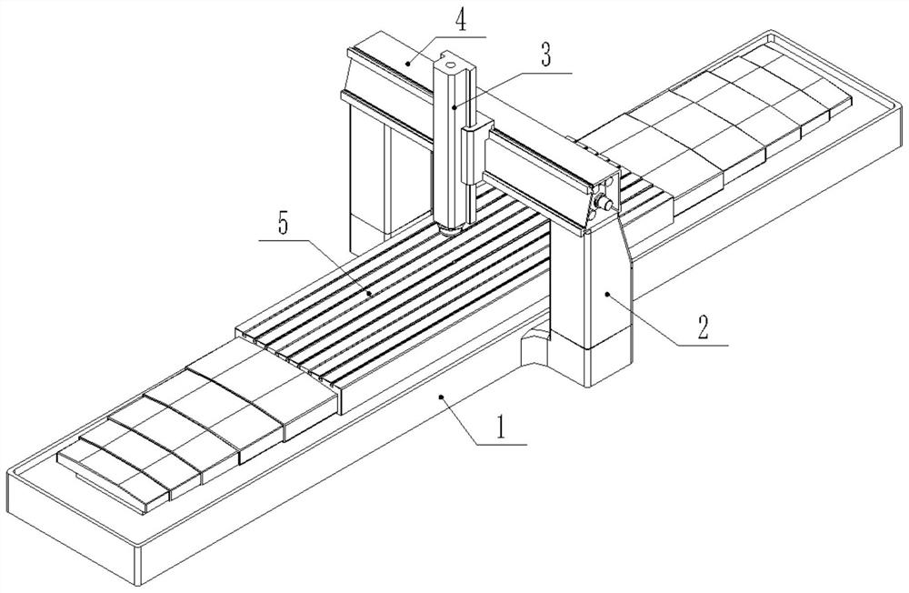
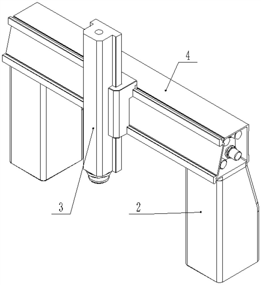
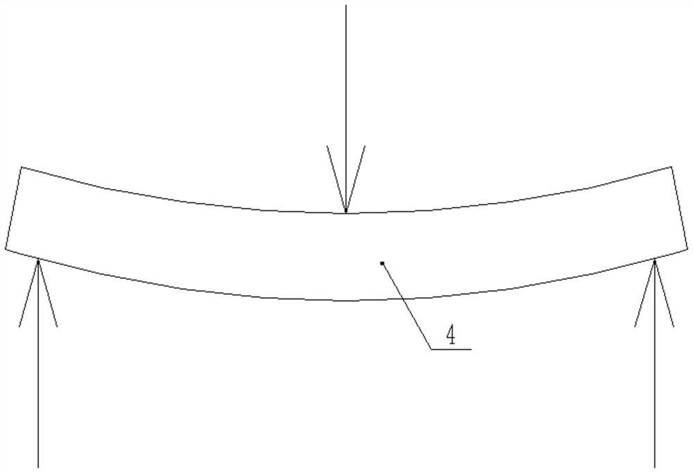
[0032] The embodiment of the present invention provides a self-aligning machine tool beam, such as Figure 2 to Figure 11 As shown, the self-aligning machine tool beam provided by the embodiment of the present invention includes a beam body 401 , a plurality of tie bars 402 , a tension device, a sensor 405 , a washer 406 and a nut 407 . like figure 2 , Figure 7 , Figure 8 As shown, the beam body 401 and figure 2 The column 2 in the middle is connected, the beam body 401 is a barrel-shaped structure with closed ends, and its cross-section (the cross-section perpendicular to the length direction of the beam is a cross-section) is a rectangle or a trapezoid, and the beam body 401 is provided with longitudinal ribs in the horizontal direction in the abdominal cavity 4011 , the longitudinal rib 4011 is placed in the middle part of the beam body 401 , and the longitudinal rib 4011 is fixedly connected with the end faces of both ends of the beam body 401 . The longitudinal ri...


PUM


Abstract

The invention discloses a self-aligning machine tool beam, comprising a beam body, a plurality of tie bars, a tension device, a sensor, a washer and a nut, wherein the beam body is a barrel-shaped structure with closed ends, and its cross section is rectangular or trapezoidal , longitudinal ribs are arranged in the horizontal direction of the abdominal cavity of the beam body; several tie bars are arranged in the abdominal cavity of the beam body along the horizontal direction, and the tie bars run through the end faces of both ends of the beam body and are distributed on the upper and lower sides of the longitudinal rib; the tension device is fixedly installed The outer end surface of one end of the beam body is used to apply tension to the tie bars, the other end of the tie bars is equipped with a nut, the back of the nut is attached with a gasket, and the other side of the gasket is attached to the outer end surface of the other end of the beam body. ; The sensor is set on the tie bar, detects the deformation of the machine tool beam in real time, and feeds back the deformation to the numerical control system. The cross beam of the machine tool is straightened by adjusting the tension of the tie bars in real time, and its rigidity and stability are further improved without increasing the difficulty of manufacturing, and it is widely used.

Description

technical field [0001] The invention relates to the field of machine tools, in particular to a self-aligning machine tool beam. Background technique [0002] A machine tool is a machine that makes machines, also known as a work machine. Due to the wide variety of machines or mechanical parts, different shapes, and different manufacturing processes, the machine tools produced according to the manufacturing process are also various, usually classified as metal cutting machine tools, Forging machines and woodworking machines, etc. There are many ways to obtain mechanical parts in mechanical manufacturing. In addition to cutting, there are casting, forging, welding, stamping, extrusion and 3D printing, etc. However, parts that require high precision and fine surface roughness are currently mainly The final machining is performed by cutting on the machine tool. Therefore, the metal cutting machine tool is the key equipment for ensuring high-precision parts or manufacturing high-...

Claims


Application Information

Patent Timeline
Patent Type & Authority Patents(China)
IPC IPC(8): B23Q1/01B23Q1/25
CPCB23Q1/015B23Q1/25
Inventor 王加祥胡明国兴洋
Owner SHANDONG MACHINERY DESIGN INST
Why Eureka
Try Eureka