Method and apparatus for improving absorptivity and emissivity in infrared thermal wave non-destructive testing
A non-destructive testing, infrared thermal wave technology, applied in the direction of material defect testing, etc., can solve the problems of pollution, damage, limit the application of infrared thermal wave non-destructive testing technology, etc., to improve the detection effect, improve the absorption rate and infrared emissivity effect.
- Summary
- Abstract
- Description
- Claims
- Application Information
AI Technical Summary
Problems solved by technology
Method used
Image
Examples
Embodiment 1
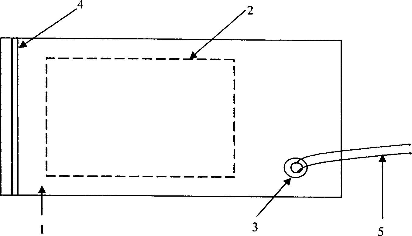
[0017] Example 1: For a vacuum coating device independent of the detection system, see figure 1 Firstly, the vacuum bag 1 of suitable material should be selected, and the material of the vacuum bag 1 is required to be a polymer film with high elasticity and high tensile strength, which has good visible light absorption rate and infrared emission rate. Put the detected object 2 into the vacuum bag 1 and seal the vacuum bag 1 with the buckle 4, pump out the air in the vacuum bag 1 through the air hole 3, so that there is no air gap between the film of the vacuum bag 1 and the detected object 2 In close contact, the air hole 3 is connected to the vacuum device through the air pipe 5 . To further increase the visible light absorption rate and infrared emission rate of the film surface, uniform spraying treatment can be carried out on the film surface.
Embodiment 2
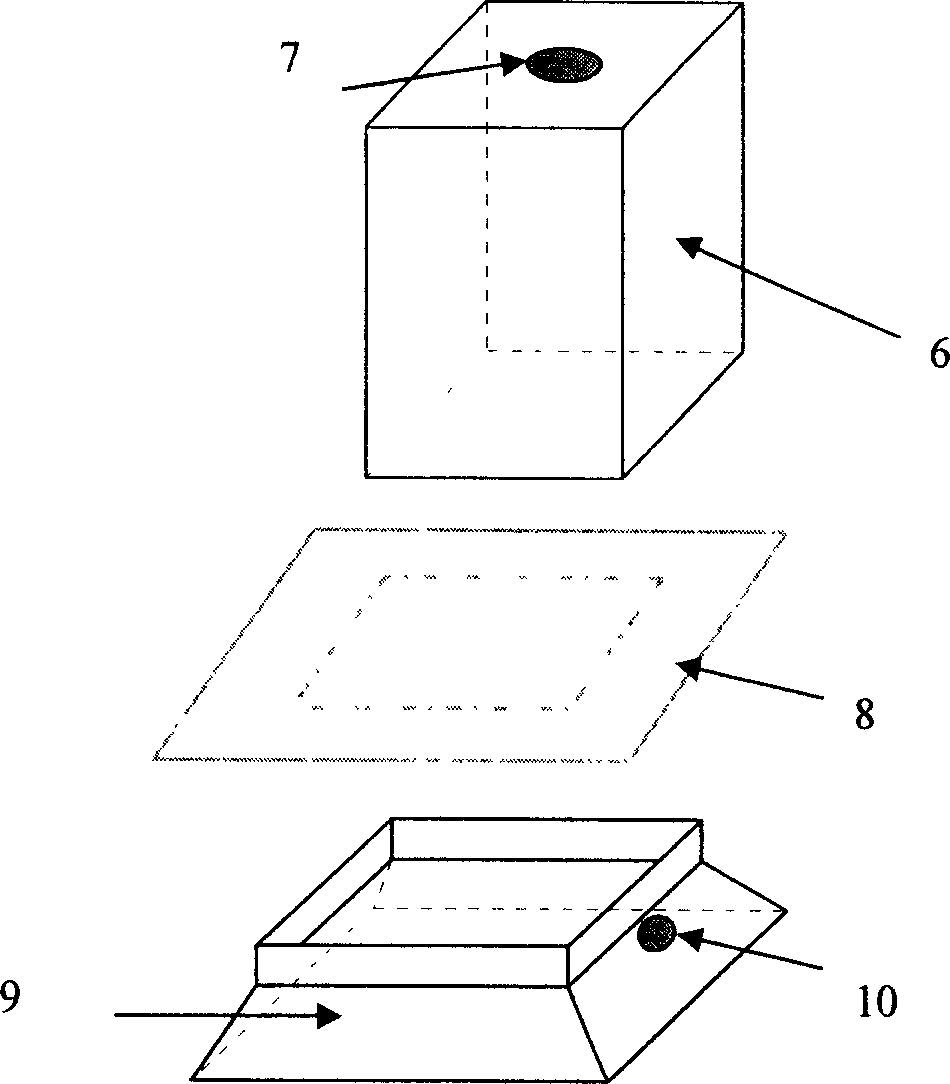
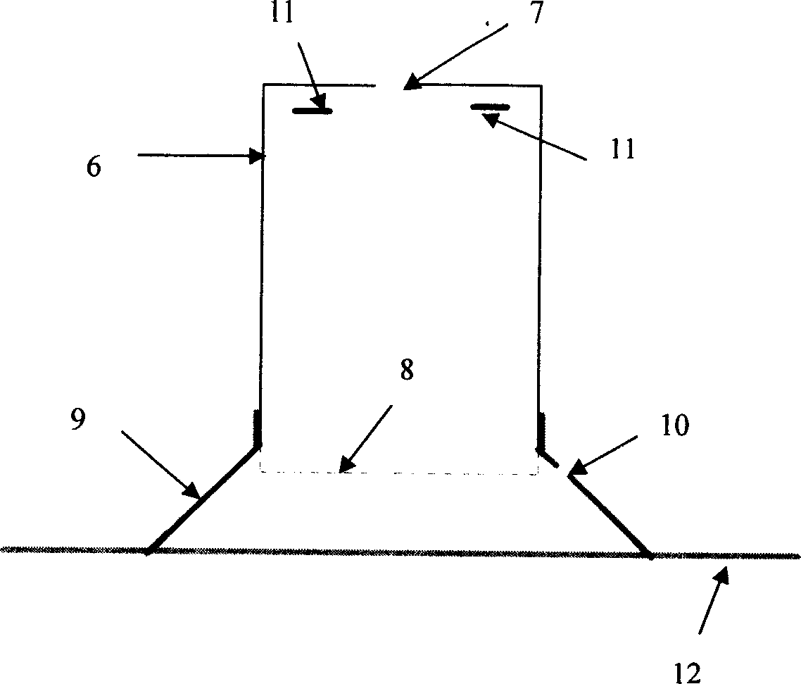
[0018] Example 2: The vacuum coating device in the infrared thermal wave non-destructive testing system see figure 2 and image 3 . Add a rubber skirt 9 between the flashlight cover 6 and the surface 12 of the object to be measured. The rubber material used to make the rubber skirt 9 should have certain elasticity. The shape and size of the upper port of the rubber skirt 9 are the same as those of the flashlight cover 6. The shape and size of the port match, and the shape and radian of the port under the rubber skirt 9 need to be designed according to the shape and surface radian of the test piece. Have air-breathing hole 10 on rubber skirt circumference 9. Cover the upper port of the rubber skirt 9 with the film 8, then insert the lower port of the flash cover 6 into the upper port of the rubber skirt 9, and at the same time clamp the film 8, during the measurement, the lower port of the rubber skirt 9 Place it on the surface 12 of the measured object, so that a closed sp...
PUM
 Abstract
Description
Claims
Application Information
 - Generate Ideas
- Intellectual Property
- Life Sciences
- Materials
- Tech Scout
- Unparalleled Data Quality
- Higher Quality Content
- 60% Fewer Hallucinations
Browse by: Latest US Patents, China's latest patents, Technical Efficacy Thesaurus, Application Domain, Technology Topic, Popular Technical Reports.
© 2025 PatSnap. All rights reserved.Legal|Privacy policy|Modern Slavery Act Transparency Statement|Sitemap|About US| Contact US: help@patsnap.com


