
Self circulated cascade gas lift type internal-loop reactor system

A reactor system and reactor technology, applied in the field of chemical engineering, can solve problems such as energy consumption, and achieve the effects of fast dissolution, low mass transfer resistance, and energy saving

Inactive Publication Date: 2006-04-26
TSINGHUA UNIV
View PDF0 Cites 12 Cited by
  • Summary
  • Abstract
  • Description
  • Claims
  • Application Information

AI Technical Summary

Problems solved by technology

In many processes, material circulation between two reactors consumes a lot of energy

Method used


Image

  • Self circulated cascade gas lift type internal-loop reactor system
  • Self circulated cascade gas lift type internal-loop reactor system
  • Self circulated cascade gas lift type internal-loop reactor system

Examples


Embodiment 1

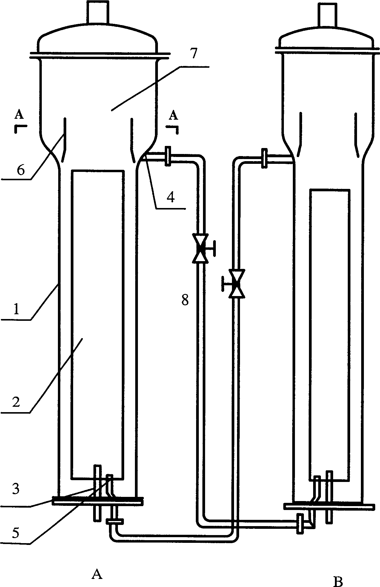
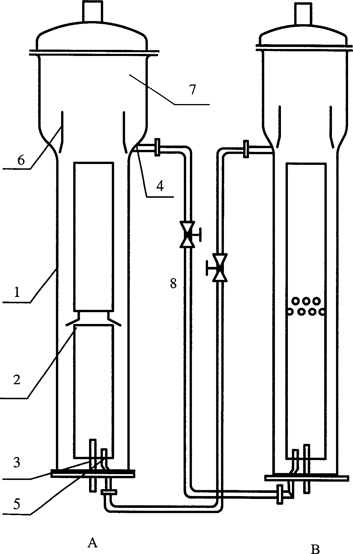
[0035] Embodiment 1: This embodiment is the change of the circulating fluid flow rate between the two reactors when the gas flow rate entering the reactor is different according to the experimental measurement. The draft tubes in the reactors tested in the experiment are all 2 levels. The main structural parameters of the reactor are listed in Table 1. The material of the reactor is plexiglass, and the material of the guide tube is stainless steel. The pipeline 8 is a nylon pipeline with a diameter of 2 cm, and a flow meter is arranged in the pipeline. The liquid used in the measurement is pure water, the gas is compressed air, and the operating pressure is normal pressure. When the volumetric gas holdup of gas in tower B remains constant (6%), and the volumetric gaseous holdup of gas in tower A ε A At different times, the flow rate L of the fluid flowing out of reactor B (fluid flowing into reactor A) B The changes are plotted in the attached Image 6 middle.

[0036] ...

Embodiment 2

[0037] Embodiment 2: This embodiment uses the reactor system of the present invention to remove hydrogen sulfide in the gas through absorption reaction and regenerate the absorbent. The process applies an iron-based process to complex Fe 3+ Catalyst for absorption reactions. Its absorption reaction and complexation of iron Fe 2+ The regeneration reaction is as follows:

[0038] The absorption reaction is:

[0039]

[0040] The regeneration reaction is:

[0041] Absorption reaction and regeneration reaction are carried out in loop reactor B of loop reactor A respectively. The hydrogen sulfide-containing gas enters the reactor A from the distributor of the reactor A, and is absorbed by the solution in A and complexed with Fe 3+ After the reaction, sulfur (S) and complexed Fe are generated 2+ ; The gas from which hydrogen sulfide is removed is discharged from the top of A. The complexed Fe formed in the reaction 2+ As the solution flows into reactor B, compre...


PUM


Abstract

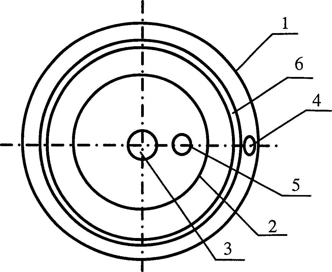
The self-circulation series air-lift inner ring current reactor system comprises two air-lift inner ring current reactors, wherein, every reactor comprises: tower body 1, draft tube 2 with liquid inlet 5, gas distributor 3, over-flow device 6 with liquid outlet 4 on bottom, and pipe 8 used to connect one outlet to inlet on another reactor; the liquid out from over-flow device contains no gas while the liquid in reactor contains some gas; in inlet 5, the liquid pressure in pipe is larger than the reactor, liquid flows into to realize material exchange and recycle without pump; the dissolve speed of gas in said reactor is quick, the adsorption and three-phase catalysis reaction have high efficiency.

Description

technical field [0001] The present invention relates to a reactor system suitable for gas and liquid absorption-desorption process or gas, liquid and solid three-phase catalytic reaction-catalyst regeneration process, in particular to a self-circulation series air-lift internal circulation reactor system, in the field of chemical engineering. Background technique [0002] Gas and liquid absorption-desorption process, gas, liquid and solid three-phase catalytic reaction-catalyst regeneration process are the two most common and basic processes in the chemical industry and petrochemical industry. Such processes generally have the following characteristics: [0003] 1) The efficiency of the absorption and reaction process is closely related to the mixing and interphase mass transfer process of gas, liquid or gas, liquid and solid. 2) Generally, at least two reactors are required to complete the above process, one reactor is an absorption or three-phase catalytic reaction react...

Claims


Application Information

Patent Timeline
IPC IPC(8): B01J10/00B01D53/18B01J8/22
Inventor 乔永蒋国强赵洲洋丁富新
Owner TSINGHUA UNIV
Learn More