
Centralizer and its manufacturing method

A manufacturing method and a technology of centralizers, which are applied in the manufacture of tools, earth square drilling, ceramic molding machines, etc., can solve the problems of affecting crude oil output, short replacement cycle, and lower production efficiency, so as to prolong the repair and maintenance cycle and reduce maintenance costs , the effect of increasing crude oil production

Inactive Publication Date: 2006-04-05
王敬东
View PDF0 Cites 5 Cited by
  • Summary
  • Abstract
  • Description
  • Claims
  • Application Information

AI Technical Summary

Problems solved by technology

The centralizers commonly used in oilfields, including the centralizers used in screw pumps imported from France and Canada, are all made of nylon or polyvinyl chloride, and the diversion grooves are generally designed as straight grooves. In actual use, Due to the poor wear resistance and high temperature resistance of nylon or polyvinyl chloride, the centralizer wears very quickly, the service life is short, and the replacement cycle is short. In addition, the pumping well must be shut down during replacement, and each repair and replacement takes 1-2 days time, affecting crude oil production and increasing maintenance costs
Because the centralizer works at a depth of 1,000 meters to 4,000 meters, people cannot observe the wear of the centralizer, let alone observe and find that the sucker rod is finely ground and the oil pipe is worn and leaked. In fact, there are a large number of The oil pipe is worn out, worn out and cannot be used, which reduces the production of the oil well, and the loss is unpredictable
Some oil field tests use steel materials to make centralizers. Although steel materials have good wear resistance, they are not corrosion-resistant and heavy. After corrosion, the surface is rough and the friction coefficient increases, which increases the cost of pumping oil accordingly. , so it is not widely used
Therefore the defect that the centralizer in the prior art exists is: because the material of making centralizer is not wear-resistant, not resistant to high temperature, not resistant to corrosion, heavy in quality, make centralizer wear fast in use, life-span is short, replacement period is short, reduce production efficiency

Method used


Image

  • Centralizer and its manufacturing method

Examples


Embodiment Construction

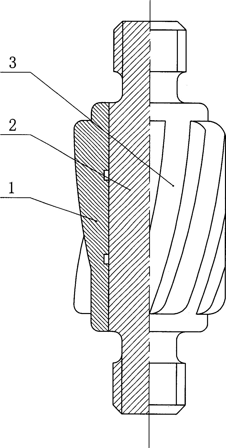
[0021] Such as figure 1 As shown, the present invention includes a centralizing block 1 and a short rod 2. The centralizing block 1 is sleeved on the outer periphery of the short rod 2 of the sucker rod. To the oblique flow guide groove 3 with a critical angle of 18 degrees. The centralizing block 1 is made of silicon nitride ceramic material.

[0022] Since the silicon nitride ceramic material has the unique properties of wear resistance, corrosion resistance, high temperature resistance and light weight, the centralizer has the advantages of not easy to wear, long life, long replacement cycle, and can improve production efficiency.

[0023] The manufacture method of above-mentioned centralizer comprises the following steps:

[0024] 1. make a mold according to the technical requirements of said righting block 1;

[0025] ② Grinding silicon nitride ceramic powder into fine powder through rough grinding and fine grinding process;

[0026] ③Put the silicon nitride ceramic f...


PUM


Abstract

The invention discloses a stabilizer and making method for supplying an uneasy abrasive, long lifespan, long replacing period, high product efficient stabilizer, which comprises the following parts: stable block (1), short rob (2) and diagonal pilot channel (3), wherein the stable block (1) is encased around the peripheral short rob (2); several diagonal pilot channels (3) are set around the stable block (1) and each channel forms a certain critical angle to the stable block (1); the stable block (1) is made of silicon nitride ceramics material which comprises the following peculiar advantages: abrasion-proof, corrosion-resisting, high temperature-resistant and light quality. The making method of the stabilizer comprises the following steps: loading the silicon nitride ceramics power in the preparing stabilizer mould; compressing the mould by 1800kg / cm2 pressure to form a pattern; finishing the stabilizer by agglomeration in 1100-1300 Deg.C. The making method contains simple process and low cost, which can be applied in the domain of oil exploitation.

Description

technical field [0001] The invention relates to a centralizer and a manufacturing method thereof. Background technique [0002] At present, there are 14 onshore oil fields in China, and each oil field has different oil well depth and oil production due to different geological conditions. Generally, the average oil well depth is between 1000 and 4000 meters. During oil production operations, inclined wells and vertical wells (directional wells) are not completely perpendicular to the ground because of their inclination, and wear occurs between the sucker rod and the inner wall of the tubing during oil pumping, causing the sucker rod to become thinner , breakage, partial wear and leakage of oil pipes, causing crude oil to leak into the ground, and at the same time causing a large number of oil pipes and sucker rods to be unusable. Every year in various oilfields across the country, a large number of oil pipes and sucker rods are worn out and cannot be...

Claims


Application Information

Patent Timeline
IPC IPC(8): E21B17/10C04B35/584B28B3/00
Inventor 王敬东
Owner 王敬东
Learn More