
Ventilation uniform petrochemical bunker

A uniform and petrochemical technology, applied in the field of silos, can solve the problems of degassing dead zone, flash explosion and ignition of materials, and difficulty in establishing back pressure, so as to achieve uniform gas distribution, improve degassing efficiency, and improve safety.

Inactive Publication Date: 2005-06-29
CHINA PETROLEUM & CHEM CORP
View PDF0 Cites 5 Cited by
  • Summary
  • Abstract
  • Description
  • Claims
  • Application Information

AI Technical Summary

Problems solved by technology

The existing high-pressure polyethylene silo has a silo body, the lower end of the silo body has a cone section, the tip of the cone section has a discharge port, the upper edge of the cone section is equipped with an annular air belt pipe, and one side of the latter There is one main air duct, and a number of reverse blowing nozzles are evenly distributed along the annular air belt tube. There is an anti-L-shaped anti-blow duct between the discharge port and one main air duct, and the discharge port passes through the reverse L-shaped air duct. The anti-blow pipe is connected with one main air pipe. The upper part of the silo has a material inlet and an air outlet. The ventilation area of ​​the blowing nozzle is larger than the area of ​​the main air duct, and the anti-L-shaped anti-air duct is also drawn from the main air duct to communicate with the upper anti-air nozzle, making it difficult to establish back pressure and cannot play a role in ventilation, forming a detachment in the cone part. Gas dead zone, causing the concentration of ethylene gas in this area to exceed the safe control range (0.5%wt), making the minimum ignition energy (MIE) of the dust in the warehouse H ) value decreases, when the upper tuyere insertion tube and the pile surface are likely to generate spark discharge and discharge along the pile surface of the material, it is easy to cause flash explosion and ignition of the material

Method used


Image

  • Ventilation uniform petrochemical bunker

Examples


Embodiment Construction

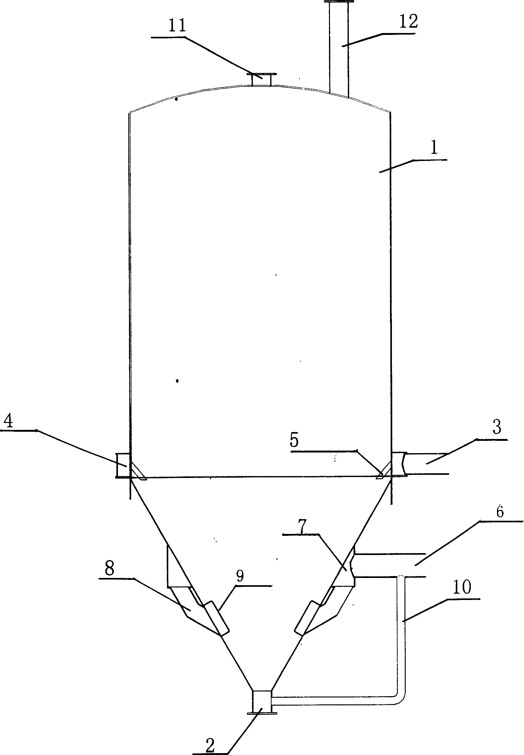
[0007] The silo of the present invention has a silo body 1, the lower end of the silo body 1 has a cone section, the tip of the cone section has a discharge port 2, the upper edge of the cone section is equipped with an annular air belt pipe 4, and one of the latter There is a main air duct 3 on the side, and 12 anti-blow air nozzles 5 are evenly distributed along the annular air belt duct 4. The upper part of the warehouse body 1 has a material inlet 11 and an air outlet 12. Two main air ducts 6 are installed on the conical surface on the same side, and there is an annular air belt pipe 7 around the cone section. Two-way reverse blowing tuyere 8, in the bottom of the two-way reverse blowing tuyere 8, a second-way reverse blowing tuyere baffle 9 parallel to the cone surface is installed inside the cone section, and the discharge port 2 passes through the reverse L-shaped The blowing pipe 10 communicates with the two-way main air pipe 6 .

[0008] When using the silo of the pr...


PUM


Abstract

The invention is a uniformly ventilating petroleum chemical bin. There is a taper section below the bin, a pouring opening at narrow end the taper section, a ring air pipe on the upper edge of the taper section, a main ventilating pipe of route one by a side of the ring pipe. Several counter-blowing tuyere noses are uniformly distributed along the ring air pipe. A feeding hole and an air gate is on the top of the bin and features that main ventilating pipe of route 2 installed on the same conical surface of route 1 connects with the ring air pipe, several counter-blowing tuyere noses of route 2 are uniformly distributed on the above cone, under these noses inside the taper section baffle board of route 2 tuyere noses is installed in a parallel with the conical surface, the pouring opening is connected to the route 2 main air pipe. The invention bin ventilates uniformly so to enhance the efficiency of exhausting, overcome the flaws of the existing bin that the ventilation is not uniform, dead band exists, the combustible gas can not be exhausted from the air gate, the gas inside the bin is hyper-concentrated, so that the bin is more safe.

Description

technical field [0001] The invention relates to a feed bin for petrochemical industry, in particular to a petrochemical feed bin with uniform ventilation. Background technique [0002] Siloes are widely used in various industries such as mining, chemical industry, food, agriculture, and ports. Silo accidents are very common in countries all over the world and have caused huge economic losses. As far as the petrochemical industry is concerned, electrostatic explosion accidents often occur in high-pressure polyethylene silos, and one of the important factors causing this accident is the high local ethylene concentration in the silo. The existing high-pressure polyethylene silo has a silo body, the lower end of the silo body has a cone section, the tip of the cone section has a discharge port, the upper edge of the cone section is equipped with an annular air belt pipe, and one side of the latter There is one main air duct, and a number of reverse blowing nozzles are evenly di...

Claims


Application Information

Patent Timeline
IPC IPC(8): B65D90/34
Inventor 张亚丽宫宏刘全桢孙立富刘宝全
Owner CHINA PETROLEUM & CHEM CORP
Learn More