
Molybdenum ferroalloy smelting sand base forming method and device

A molding device, a molybdenum-iron alloy technology, which is applied in basic structural engineering, construction, etc., can solve the problems of non-smooth side surface of discus and sticky slag, low density and strength of sand base, and poor control of dry humidity of sand base. Excellent working environment, improved sand base strength, simple structure

Active Publication Date: 2017-03-15
洛阳栾川钼业集团冶炼有限责任公司
View PDF5 Cites 0 Cited by
  • Summary
  • Abstract
  • Description
  • Claims
  • Application Information

AI Technical Summary

Problems solved by technology

At present, domestic ferromolybdenum smelting sand bases are generally made manually, which is time-consuming and labor-intensive. Due to the disordered operation and the lack of strict control of the dry humidity of the sand base, the quality of the sand base will decline and the shape of the sand base will be uneven. It is easy to induce the phenomenon of running furnace, furnace leakage, segregation of ferromolybdenum element, excessive sand material consumption, etc.
Foreign countries use fixed mold operation to make sand base, but due to the need to use self-fluxing steel molds, the operation is inconvenient and the cost is greatly increased
Even if the more advanced sleeve-type equipment is used to make the sand base, although the standardization of the sand base can be effectively controlled, there are disadvantages such as high equipment manufacturing cost, cumbersome operation, low density and strength of the sand base, and poor air permeability, resulting in the discus side surface Unsmooth and sticky slag will affect the quality of ferromolybdenum, increase the finishing rate, reduce the metal recovery rate, and bring great inconvenience to the standardization of smelting operations and the improvement of production indicators

Method used


Image

  • Molybdenum ferroalloy smelting sand base forming method and device
  • Molybdenum ferroalloy smelting sand base forming method and device
  • Molybdenum ferroalloy smelting sand base forming method and device

Examples


Embodiment Construction

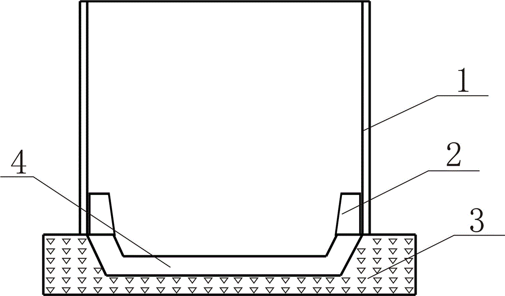
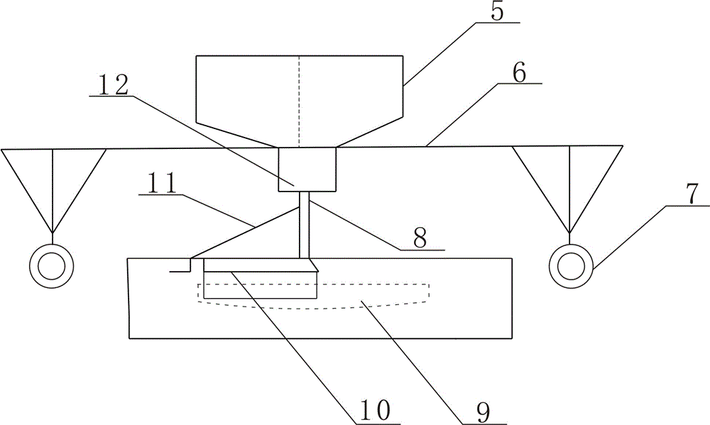
[0037] The technical solution of the present invention will be described in further detail below in conjunction with the accompanying drawings and embodiments.

[0038] A sand-based forming method for ferromolybdenum alloy smelting, which comprises the following specific steps:

[0039] Step 1. Preparation of sand base materials

[0040] Quartz sand and adhesive are mixed evenly according to the mass ratio (3-6): (0.5-1.2), and stand at room temperature for 10-20 minutes to form a rigid skeleton; among them, the water content of quartz sand is 2-3%, and the quartz sand grain The particle size is 10-50 mesh, the active ingredient content of the binder is more than 85%, and the particle size is 5-20 mesh;

[0041] Step 2. Sand-based dynamic molding

[0042] The sand-based foundation is first tiled with quartz sand with a thickness of 40-50 cm and a particle size of 5-10 mm, which is used as the bottom initial mold 3. The mixture is quantitatively and evenly arranged on the bo...


PUM

PropertyMeasurementUnit
particle sizeaaaaaaaaaa

Abstract

The invention discloses a ferro-molybdenum alloy smelting sand foundation forming method. The method comprises the steps that firstly, sand foundation materials are prepared; a sand foundation forming device is utilized to conduct circumferential rotation movement in the radius direction of a sand foundation to quantitatively and evenly distribute the sand foundation materials on a bottom layer blank mold of the sand foundation; drawing forming, compaction and densification of an inner mold are conducted; a smelting furnace tube is installed on the sand foundation after drawing is conducted and it is ensured that a mold stripping connection ring on the upper portion of the sand foundation and an inner ring on the lower portion of the furnace tube are tightly connected; and strong air drying and curing are conducted, moving mold forming of the sand foundation is completed, and then furnace burdens are put to smelt ferromolybdenum. The invention further discloses the ferro-molybdenum alloy smelting sand foundation forming device. The degree of automation is high; the procedures are conducted furnace by furnace to achieve the assembly line work; the sand foundation is standard, the surface is smooth, flat and good in air permeability, the sand consumption is controlled accurately, the work environment is good, personnel configuration is reduced, labor intensity is relieved, the iron and slag separating degree is good, and the ferro-molybdenum production comprehensive index is improved.

Description

technical field [0001] The invention belongs to the technical field of ferromolybdenum alloy smelting, and in particular relates to a sand-based forming method and device for ferromolybdenum alloy smelting. Background technique [0002] The production of smelting sand base is an important link in the ferromolybdenum smelting process. At present, domestic ferromolybdenum smelting sand bases are generally made manually, which is time-consuming and labor-intensive. Due to the disordered operation and the lack of strict control of the dry humidity of the sand base, the quality of the sand base will decline and the shape of the sand base will be uneven. It is easy to induce phenomenon such as running furnace, leaking furnace, segregation of ferromolybdenum element, excessive sand material consumption and cost increase. Foreign countries use fixed mold operation to make sand base, but due to the need to use self-fluxing steel molds, the operation is inconvenient and the cost is g...

Claims


Application Information

Patent Timeline
Patent Type & Authority Patents(China)
IPC IPC(8): E02D27/44E02D15/02C22C1/02C22C27/04
Inventor 朱要武张五兴刘玲王宏雷郑春晓王松坡杨军方张建新王松涛
Owner 洛阳栾川钼业集团冶炼有限责任公司
Learn More