
Method for driving induction motor

A technology of induction motor, driving method, applied in the direction of starter, motor generator/starter, motor generator control, etc. of a single polyphase induction motor, which can solve trial errors, difficult to achieve optimal adjustment, long time, etc. problem, to achieve the effect of large output torque

Inactive Publication Date: 2005-04-13
TSUDAKOMA KOGYO KK
View PDF3 Cites 10 Cited by
  • Summary
  • Abstract
  • Description
  • Claims
  • Application Information

AI Technical Summary

Problems solved by technology

[0008] In the loom, because of these circumstances, it is necessary to quickly switch the number of revolutions of the loom according to the switching of the weaving conditions such as the fabric structure and the selection of the weft yarn, but on the main shaft of the loom, a weft beating device and a warp opening device, etc. are connected , with very large inertia
Therefore, for example, even if the number of revolutions of the loom is switched to a high number of revolutions, and the output frequency is switched from the current low value to a higher value, the output voltage corresponding to the normal state in which the output frequency has been changed is still supplied. In such a conventional method, sufficient acceleration torque cannot be obtained, and there is a problem that it takes a long time (actually, several picks are required) until the final target rotation speed is reached.
In this way, when it takes time to change the number of revolutions, the weaving conditions (for example, weft insertion conditions) corresponding to the transition period of the number of revolutions change need to be specially set. The setting of weaving conditions during the transition period like this will often occur in practice. Trial and error, difficult to achieve optimal adjustment

Method used


Image

  • Method for driving induction motor
  • Method for driving induction motor
  • Method for driving induction motor

Examples


no. 1 Embodiment

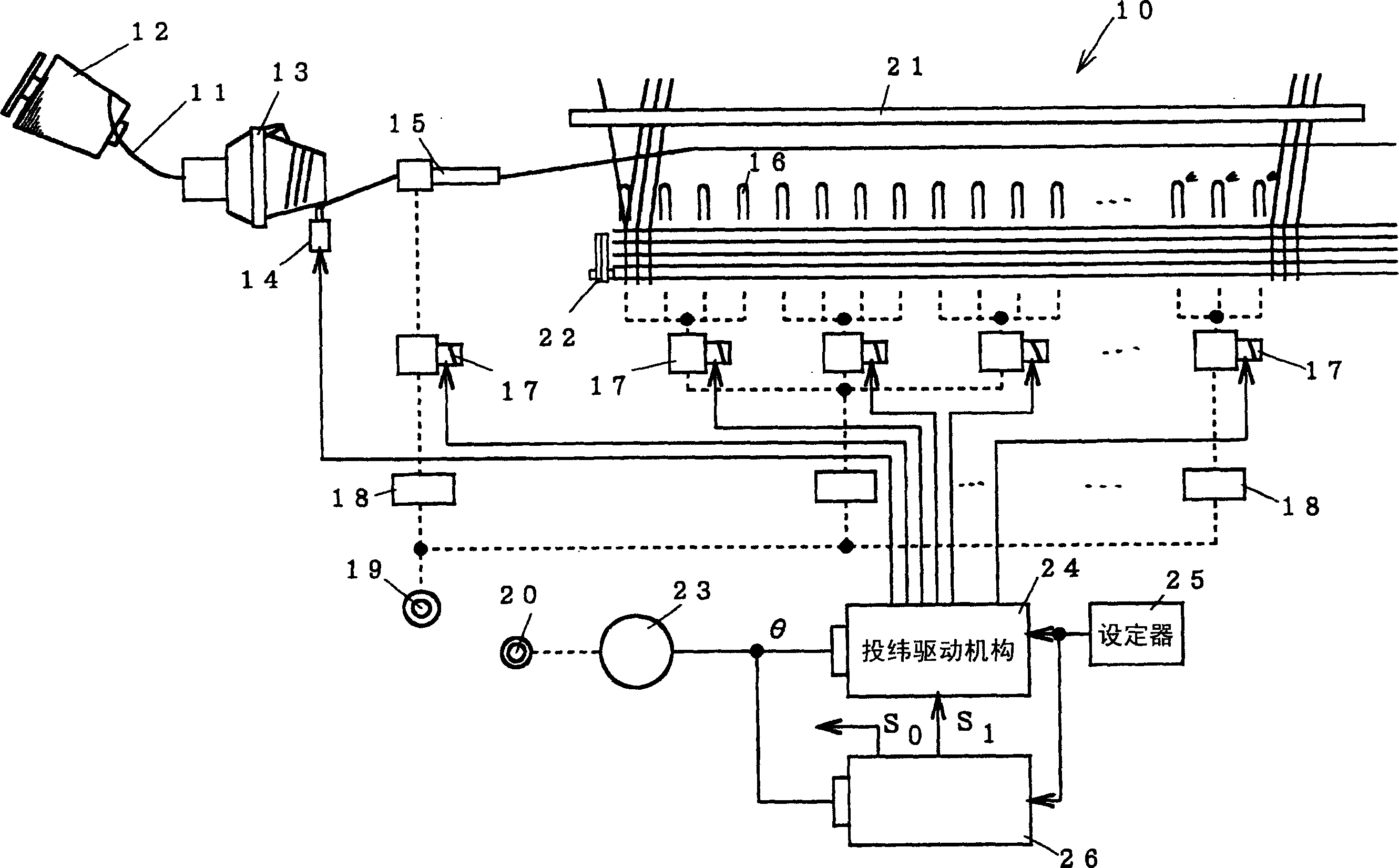
[0037] Hereinafter, specific embodiments of the present invention will be described with reference to the drawings. figure 1 It represents a kind of loom in fiber machinery, and more specifically, it represents the multi-color weft insertion that switches the number of revolutions of the loom while switching the weft yarn type of a weaving condition corresponding to the number of weft insertion and picks. Air jet loom.

[0038] In the loom 10, there is a yarn feeding body 12 for supplying the weft yarn 11, a weft yarn length measuring device 13, a stop pin 14 arranged thereon, and a main nozzle 15 for weft insertion of the weft yarn 11 by air jetting and a controlled A plurality of sub-nozzles 16 are arranged in the warp yarn opening on the way of the flying weft yarn and assist the flying weft yarn 11 by spraying air. The main nozzle 15 is connected to a pressure regulating device 18 constituted by, for example, an electropneumatic proportional valve or the like via an elect...

no. 2 Embodiment

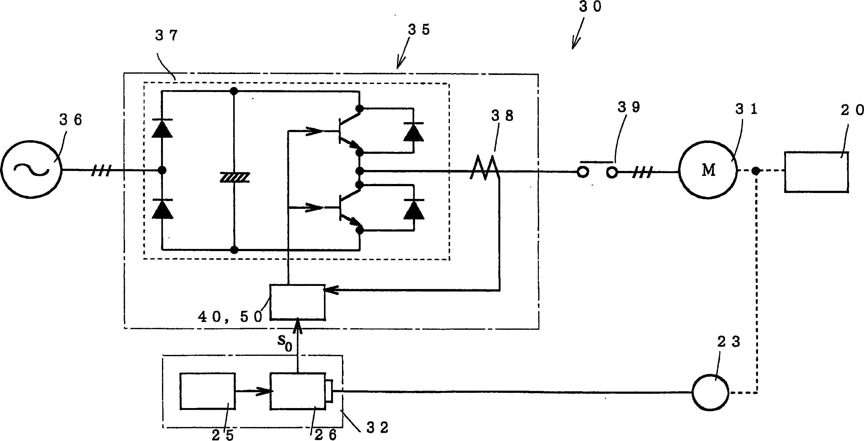
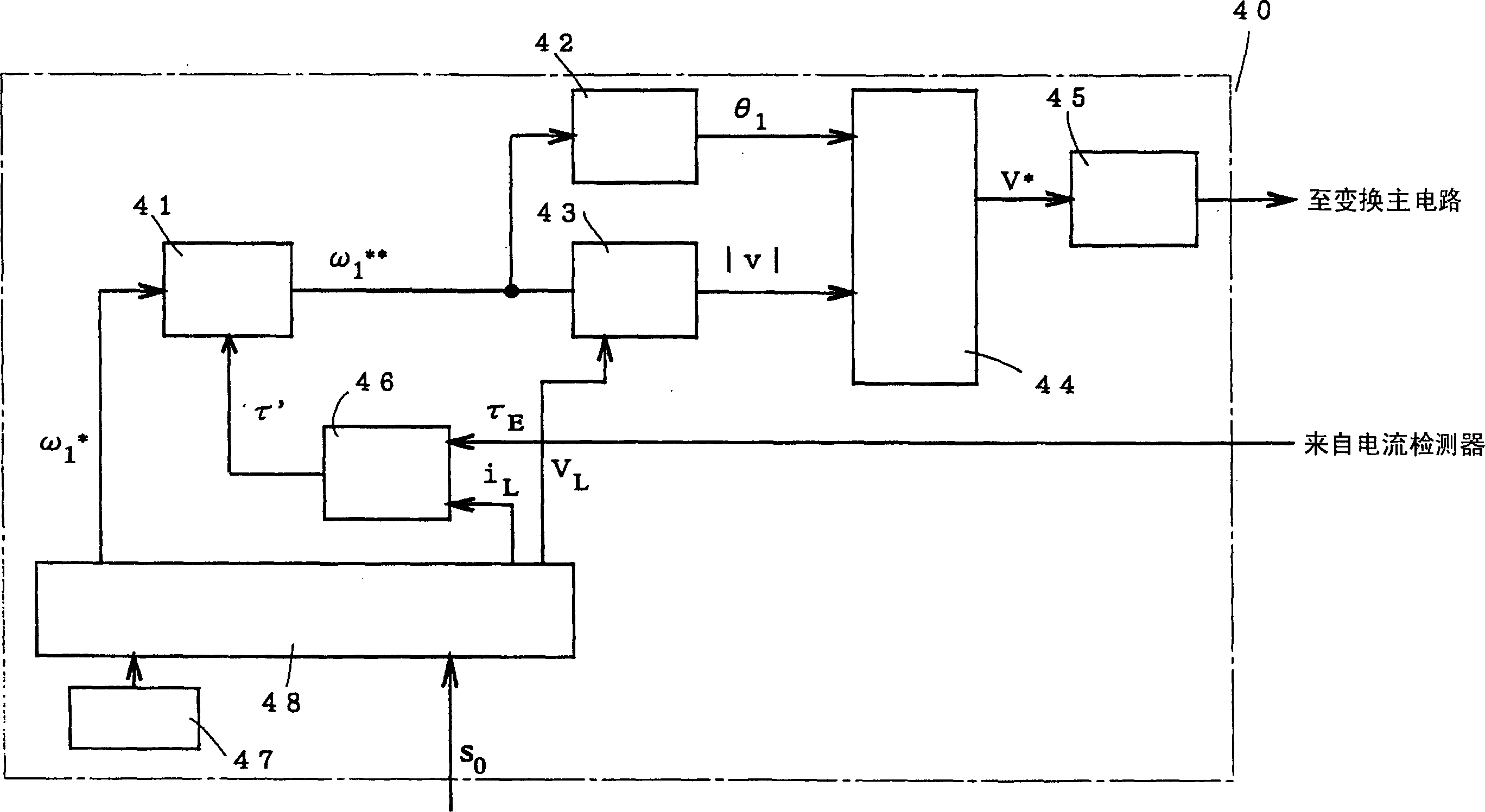
[0062] As the conversion device, besides a device in which the output voltage is controlled by so-called V / f, a device in which the output voltage is controlled by vector calculation can also be used. Figure 11 The internal block diagram of the control circuit 50 using such a conversion device is shown, and more specifically, the slip frequency ω detected as the rotation speed of the induction motor 31 is shown. S , and by making the slip frequency ω S Corresponding to the changed frequency setting value and exceeding the determined specified value ω S0 , A circuit that can return to the normal state voltage. and compared to image 3 , adding a vector operator 52, a coordinate converter 51, and a slip frequency arrival detector 53 with the same function as the above-mentioned comparator 55, for the other parts, because and image 3 The parts shown have the same functions, so the same symbols are attached and explanations thereof are omitted.

[0063] In the control circui...


PUM


Abstract

A driving method of an induction motor, in which a driving device for an induction motor that drives a polyphase induction motor to rotate by outputting an AC voltage of an output frequency determined according to an operating speed from a variable voltage and variable frequency conversion device executes the first step 1st step and 2nd step, wherein, in the 1st step, during steady operation, the output frequency is set from the 1st frequency setting value to the 2nd frequency setting higher than the 1st frequency setting value When the value is switched and the induction motor is accelerated, the conversion device, when increasing the output frequency to the second frequency setting value, increases the output voltage to an overvoltage state output compared with the usual one; in the second step , and then maintain the output frequency at a value corresponding to the second frequency setting value and return the output voltage to a normal state. Accordingly, when the induction motor that has already been started and is in a stable operating state is accelerated from the current rotational speed to a higher rotational speed than this, the time required for acceleration can be shortened.

Description

technical field [0001] The present invention relates to an induction motor driving technique using a variable voltage variable frequency conversion device for supplying an AC voltage to an induction motor, and particularly relates to a method for accelerating an induction motor that has been started and is in a rotating state from the current rotational speed to a higher speed than the current one A technology that shortens the time required for acceleration. Background technique [0002] In general production machinery, induction motors are widely used to drive spindles. For example, in fiber machinery, especially in looms, due to the corresponding weft insertion speed and fabric specifications, it is necessary to set the number of revolutions of the loom (that is, the speed of the loom), so by changing the induction motor connected to the power frequency The outer diameter of the pulley on the output shaft is used to set the speed. However, in recent years, instead of the...

Claims


Application Information

Patent Timeline
IPC IPC(8): D03D51/02D03D51/00H02P1/30H02P21/00H02P21/22H02P23/07H02P23/20H02P25/026H02P27/04H02P27/08
CPCD03D51/12H02P23/0004H02P27/047H02P23/20D03D51/00H02P1/30
Inventor 高岛淳高野敏雄加藤宏明
Owner TSUDAKOMA KOGYO KK
Learn More