
Capacitance dynamic quantity sensor

一种电容型、传感器的技术,应用在传感器领域,能够解决电极厚度波动、固定电极变厚等问题

Inactive Publication Date: 2005-03-09
SII SEMICONDUCTOR CORP
View PDF1 Cites 1 Cited by
  • Summary
  • Abstract
  • Description
  • Claims
  • Application Information

AI Technical Summary

Problems solved by technology

Therefore, the entire fixed electrode becomes thick, so that fluctuations in electrode thickness easily occur

Method used


Image

  • Capacitance dynamic quantity sensor
  • Capacitance dynamic quantity sensor
  • Capacitance dynamic quantity sensor

Examples


Embodiment Construction

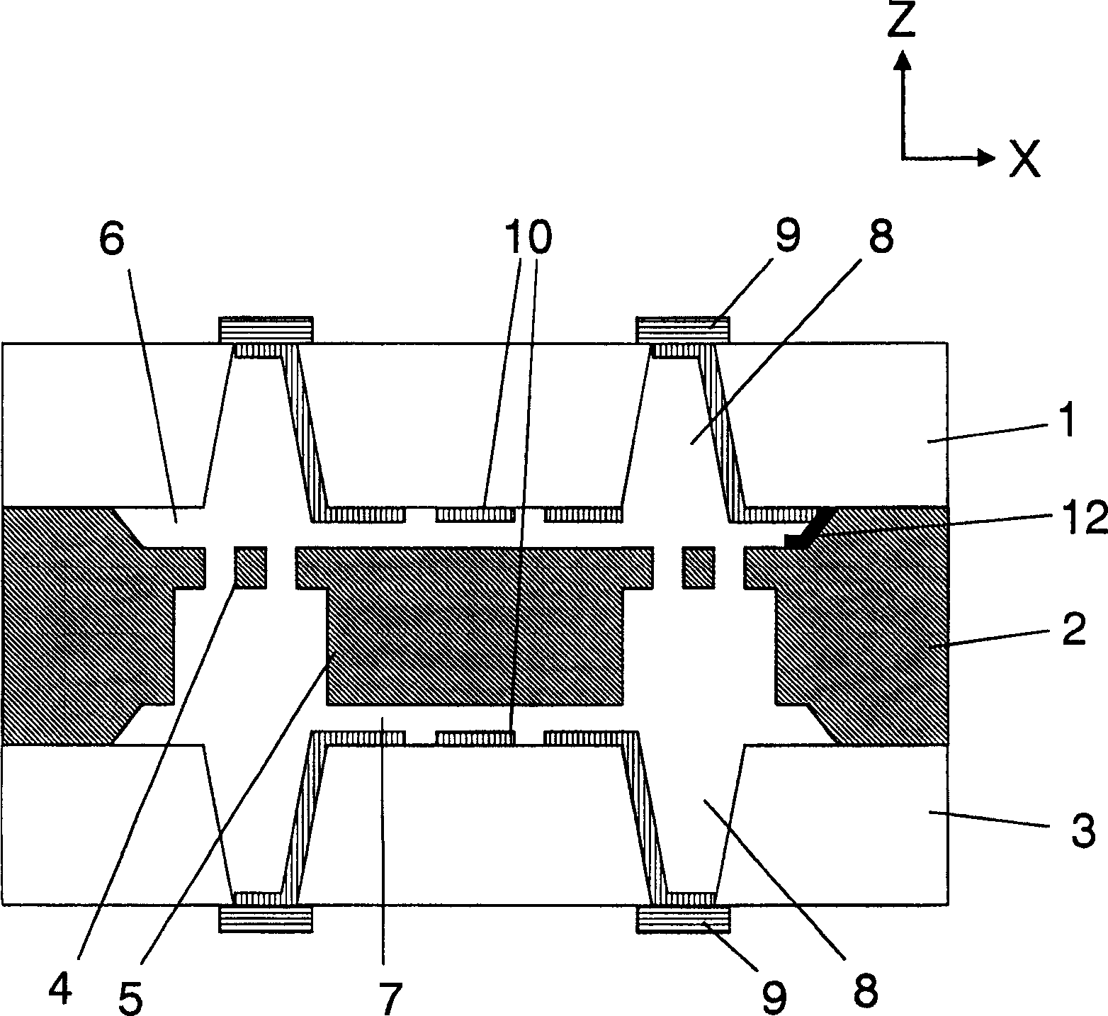
[0018] Preferred embodiments of the present invention will be described in detail below by taking a typical angular velocity sensor as an example of a capacitive dynamic quantity sensor of the present invention with reference to the accompanying drawings.

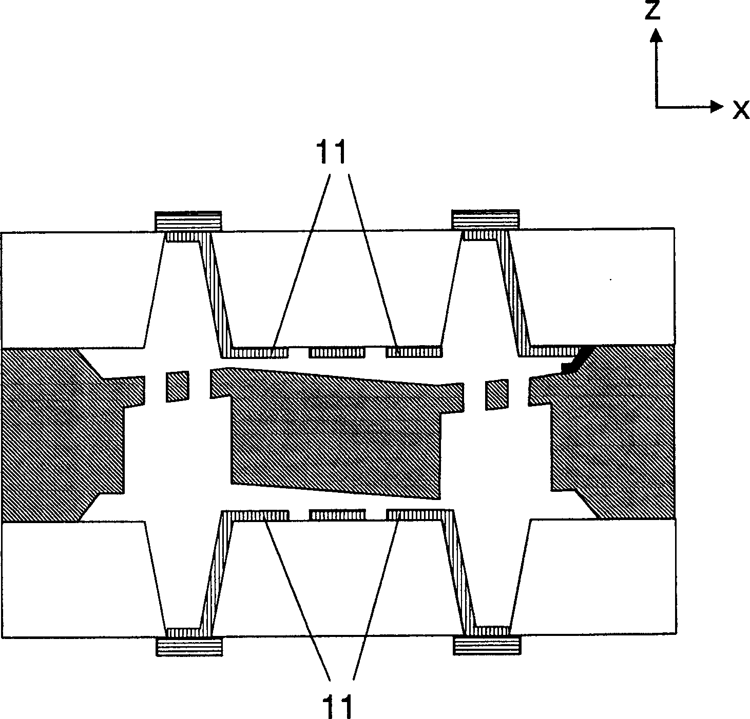
[0019] first, figure 1 A schematic cross-sectional view of a capacitive dynamic quantity sensor according to an embodiment of the present invention is shown. refer to figure 1 , this capacitive dynamic quantity sensor has a three-layer structure including an upper glass substrate 1 , a silicon substrate 2 and a lower glass substrate 3 . These three substrates 1, 2 and 3 are bonded to each other to form a three-layer structure. A vibrating element with a beam 4 and a weight 5 is formed in the silicon substrate 2 by an etching process. The vibration element can vibrate or twist due to a force applied from the outside. The shape of each beam 4 is designed to be related to its thickness, length and width, and the shape of t...


PUM


Abstract

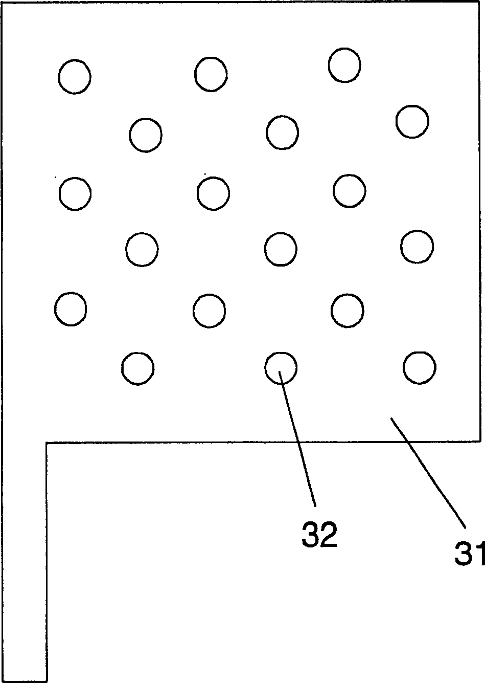
A pattern of grooves or holes is formed in metallic electrodes disposed in upper and lower sides with respect to a vibration member in a capacitance type dynamic quantity sensor. As a result, even when an electrode made of a single electrically conductive material such as Al is used, it is possible to avoid the generation of hillocks on the surface of the electrode, and film-peeling risk of the electrode can be reduced. In addition, the manufacturing cost can also be reduced.

Description

technical field [0001] The present invention generally relates to sensors for detecting dynamic physical quantities such as acceleration or angular velocity. In particular, the present invention relates to a capacitive type dynamic quantity sensor for detecting a dynamic physical quantity by detecting a change in capacitance due to movement of a structure manufactured in a semiconductor process. Background technique [0002] Heretofore, a capacitive dynamic quantity sensor is known, in which a weight adapted to move due to acceleration or angular velocity applied from the outside and a beam for supporting the weight are formed in a semiconductor substrate to detect A change in capacitance obtained between a movable electrode of an object and a fixed electrode formed at an extremely minute interval from the movable electrode (refer to, for example, JP08-094666A). FIG. 7 is a cross-sectional view showing the structure of a conventional capacitive dynamic quantity sensor. In ...

Claims


Application Information

Patent Timeline
Patent Type & Authority Applications(China)
IPC IPC(8): G01P3/44G01C19/56G01C19/5719G01P15/125H01L29/84
CPCG01P15/125G01C19/5719G01P2015/084H01L29/84
Inventor 加藤健二须藤稔枪田光男
Owner SII SEMICONDUCTOR CORP
Learn More