
Built-in type jet nozzle for laser melting and coating

A laser cladding and built-in technology, which is applied in the direction of fusion spraying, laser welding equipment, manufacturing tools, etc., can solve the problems of inconvenient processing, high surface of parts, and difficult manual operation by operators, so as to solve the problem of burning and Effects of damage, improvement of service life, and cost reduction

Active Publication Date: 2005-01-26
TECH LASER TECH SHANGHAI CO LTD
View PDF0 Cites 28 Cited by
  • Summary
  • Abstract
  • Description
  • Claims
  • Application Information

AI Technical Summary

Problems solved by technology

[0004] However, the existing side-axis nozzles have two disadvantages: first, the position of the nozzle must be adjusted manually, which is very inconvenient in many cases. For example, when performing laser cladding on large mechanical parts, the surface of the workpiece often needs Preheating to reduce cracking or increase cladding speed
However, the temperature of the surface of the part is too high, or the size is too large, making it difficult for the operator to get close to the nozzle for manual operation
Second, the volume occupied by the powder feeding pipe and the nozzle is too large, which not only brings inconvenience to the addition of a water cooling system, but also when laser cladding is performed on the surface of parts with complex shapes, the powder feeding pipe often becomes an obstacle to the movement of the laser processing head. Inconvenience to the processing
[0006] However, the obvious disadvantage of the coaxial powder feeding method is that the appearance quality of the laser cladding layer is poor
In this way, the alloy powder falling on the front of the molten pool can absorb sufficient laser energy to form a cladding layer, and part of the alloy powder falling on the rear end of the molten pool adheres to the surface of the solidifying molten pool because of insufficient laser energy, making Alloy powder utilization and surface quality degradation of laser cladding layer
[0007] It must be pointed out that although the existing coaxial powder feeding nozzles are being continuously improved and perfected, there has been no substantial improvement in the situation that the outer surface of the laser cladding layer is easy to adhere to the alloy powder.
Moreover, in the existing coaxial nozzles at home and abroad, the protective gas is blown down along the optical axis, which will cause great interference to the powder beams sent by the coaxial nozzles to gather at the laser spot, which is not conducive to laser cladding process
Sometimes, in order to ensure the stability of the sprayed powder, it is often necessary to adjust the flow rate of the protective gas to a small value, so that the protection of the focusing lens is not sufficient
Another Achilles heel of the existing coaxial nozzles is that the integration of water, air and powder in the nozzle system is not high, and the cooling water mechanism is exposed to the position that is easily irradiated by the reflected laser, and there are hidden dangers in the long-term production process. It is difficult to fundamentally meet the stability and reliability requirements of industrial applications

Method used


Image

  • Built-in type jet nozzle for laser melting and coating
  • Built-in type jet nozzle for laser melting and coating
  • Built-in type jet nozzle for laser melting and coating

Examples


Embodiment Construction

[0022] The present invention will be further described in detail below in conjunction with examples and drawings.

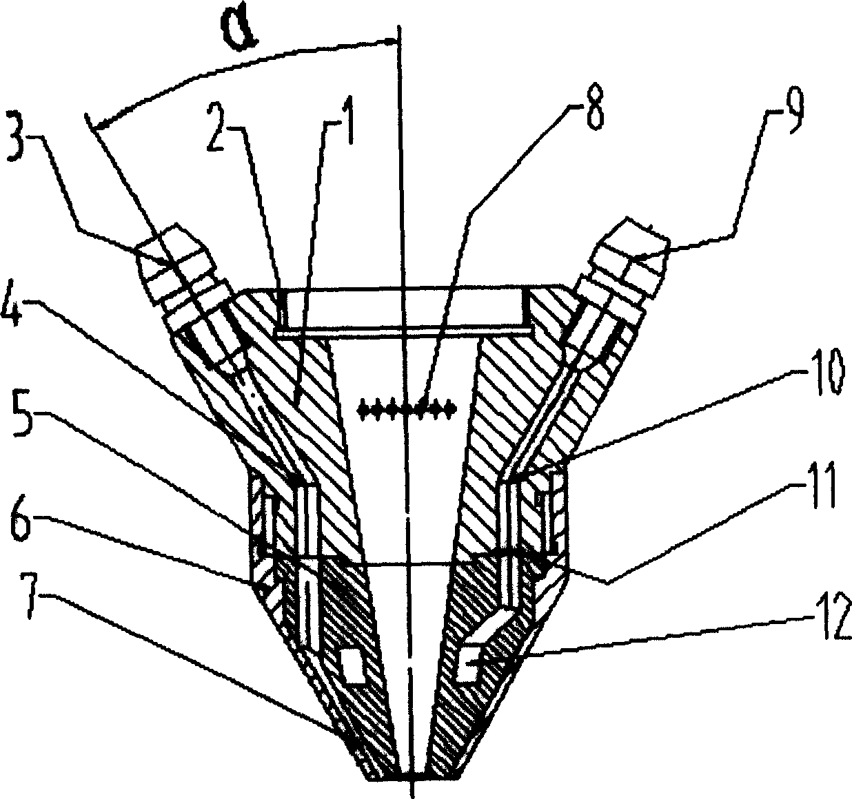
[0023] As shown in the figure, the wall of the tapered cylinder is provided with a powder channel 4, a cooling water channel 10 and a protective gas channel. The cone body is composed of upper and lower parts, namely, the upper cone 1 and the lower cone formed by the lower inner cone 5 and the lower cone sleeve 6. The upper cone cylinder 1 and the lower cone sleeve 6 are connected by threads and are positioned by positioning pins. The powder channel inlets 3 are distributed on the upper circumference of the upper cone 1, and the powder channel outlets 7 are evenly distributed on the lower circumference of the lower cone. The angle between the axis of the connecting part of the powder passage 4 and its inlet 3 and the center axis of the nozzle is between 30-70°. A cooling water ring 12 is built in the bottom of the lower inner cone 5, and the cooling water ring 12 is ...


PUM


Abstract

The invention discloses a built-in laser cladding nozzle. A powder channel, a cooling water way and a shielding gas channel are arranged in the wall of the tapered drum; the outlets of the power channel are distributed uniformly on the bottom circle of the tapered drum, and the other outlets and inlets are arranged uniformly on the upper circle of the tapered drum; the included angle Alpha between the axis of the powder and the axis of the nozzle center is in a range of between 30 degree and 70 degree; a cooling water ring connected with the cooling water way is arranged in the bottom wall of the tapered drum; and the horizontal shielding gas screen for protecting the condensing lens system consists of an air inlet, a connection channel, an air box, exhaust holes, and an air outlet. The nozzle can be used as not only side axial powder-feeding nozzle, but also coaxial powder-feeding nozzle.

Description

Technical field [0001] The invention belongs to the field of laser processing applications, and specifically relates to a laser cladding nozzle. Background technique [0002] As an advanced manufacturing technology, laser processing is being used more and more widely in industrial production. Laser processing technology covers a wide range of fields, including laser quenching, laser cladding and laser welding. The most commonly used method in laser cladding technology is the automatic powder feeding method, that is, according to the required thickness of the cladding layer, an automatic powder feeder is used to transport a certain weight of alloy powder to the laser action area on the surface of the workpiece. Among them, the shape and size of the nozzle in the automatic powder feeder are the key factors that determine the uniformity and continuity of the cladding layer and the utilization rate of alloy powder in the laser cladding process. Laser cladding automatic powder feeding...

Claims


Application Information

Patent Timeline
Patent Type & Authority Applications(China)
IPC IPC(8): C23C24/10
Inventor 胡乾午曾晓雁
Owner TECH LASER TECH SHANGHAI CO LTD
Learn More