Shell expansion type rock bolt

An expanding-shell, bolting technology, applied in the installation of bolts, construction, mining equipment, etc., can solve problems such as cracking, corrosion of steel bars, and limited length of bolts, and achieve simple construction technology, improved service life, and cost-effectiveness. superior effect

Active Publication Date: 2004-11-10
项小珍 +4
View PDF3 Cites 40 Cited by
  • Summary
  • Abstract
  • Description
  • Claims
  • Application Information

AI Technical Summary

Problems solved by technology

The disadvantages are: 1) It is difficult to guarantee the fullness of the slurry, and because of the deviation phenomenon when inserting the steel bar, the thickness of the steel bar protective layer is not easy to be uniform, and the anchoring force is not large
Corrosion and destruction of steel bars
2) At the same time, because prestressing cannot be implemented, the grouting body cracks with the deformation of the steel bar, so that water vapor directly invades the steel bar, affecting the service life
3) Not suitable for broken ground
4) Since the bolt support force is formed after the mortar is slowly hardened, it is not suitable for occasions where the support force needs to be formed quickly
[0007] 2. Early-strength cement drug coil anchor and resin drug coil anchoring fully bonded solid anchor: Although the ordinary mortar solid anchor has been improved, the range of applicable strata is expanded and the supporting force can be quickly formed, but the anchor slurry The fullness of the body and the thickness of the steel protection layer are still difficult to guarantee due to structural problems, which affects the reliability of the bolt body
When there is a lot of groundwater, even if the integrity of the rock is very good, the early-strength anchoring agent is affected by the groundwater, making the support unreliable or difficult to form a support force
[0022] (4) The length of the anchor rod is limited
In engineering practice, it is found that when the length of the anchor rod is more than 5m, the anchor rod body often cannot sufficiently stir the anchoring agent of the early-strength anchorage section during the installation of the anchor rod, which affects the anchoring force and reliability.
Limits the use of long anchors, especially as prestressed anchors

Method used


Image

  • Shell expansion type rock bolt
  • Shell expansion type rock bolt
  • Shell expansion type rock bolt

Examples


Embodiment Construction

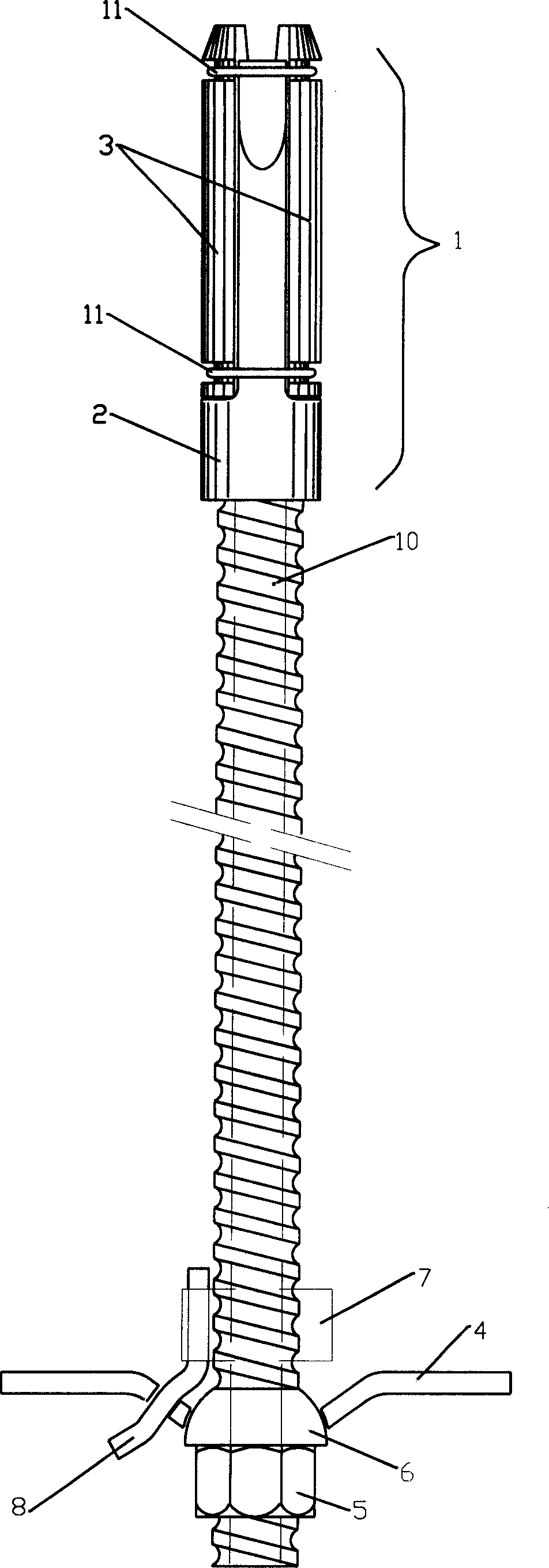
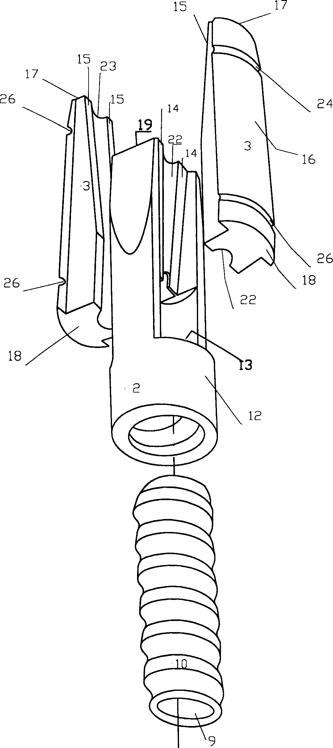
[0042] As shown in the figure, a shell-expanding anchor rod is composed of a shell-expanding anchor head 1, an anchor body 10, a support plate 4, a fastening nut 5, a washer 6, and a connecting pipe 8. The shell-expanding anchor head 1 is composed of Wedge 2 and two-petal expansion shell clips 3 are composed. The expansion shell clips 3 are fixed in the opening grooves 13 on both sides of the expansion shell inner wedge 2 through binding ropes 11. The lower part of the expansion shell inner wedge 2 is connected with the anchor rod body 10 Connection, both sides of the upper part are open grooves 13, and the middle part of the upper end of the open groove 13 has an inclined plane wedge 14, forming a double-sided wedge-shaped sliding groove 20; the inner side of the expansion shell clip 3 has an inclined plane 15 that matches the inclined plane wedge 14; the anchor rod body 10 After the top enters the inner wedge 2 of the expansion shell, it can cooperate with the lower end surfa...


PUM


Abstract

The invention is a case expanding anchor shank, composed of case expanding anchoring head, anchor shank body, supporting backing plate, fastening nut, washer, and connecting pipeline, where the anchoring head is composed of inner wedge and two clamp pieces, the clamp pieces are fixed in the open slots on two sides of the inner wedge, the lower part of the inner wedge is connected with the anchor shank body, two sides of the top of the inner wedge have the open slots with inclined wedges in the middle of the top, forming double-face wedge sliding slots; the insides of the clamp pieces have inclines to cooperate with the inclined wedges, respectively. The anchor shank is installed and can rapidly form shoring anchoring force, to control rock mass deformation, both acting as permanent both temporary shoring and can be applied to shoring on most conditions of lithoid surrounding rock.

Description

technical field [0001] The invention belongs to the technical field of geotechnical engineering anchoring support, and relates to a shell-expanding anchor rod, which is suitable for stratum structure support in underground engineering, mining engineering, foundation pit and slope engineering, and the like. Background technique [0002] In the process of underground engineering, mining engineering, foundation pit and slope engineering involved in geotechnical engineering, in order to prevent the formation from deforming, collapsing or destabilizing and endangering safety, a main support technology for strengthening the formation is to use bolts. Through the high-strength tensile capacity of the bolt installed in the formation and the dense combination between the bolt and the grouting body around the anchor and the formation, the formation is strengthened to improve the integrity of the formation and play a role. Various mechanical effects such as shear resistance, tension re...

Claims


Application Information

Patent Timeline
IPC IPC(8): E02D5/74E21D20/00E21D21/00
Inventor 吴德兴
Owner 项小珍
Why Eureka
Try Eureka