
Waste gas purification system

An exhaust gas purification system and exhaust channel technology, applied in exhaust treatment, electrical control, exhaust devices, etc., can solve the problems of easy natural ignition of fuel, etc., to eliminate engine flameout, prevent melting accidents, and suppress exhaust pressure the effect of rising

Inactive Publication Date: 2004-08-04
ISUZU MOTORS LTD
View PDF1 Cites 25 Cited by
  • Summary
  • Abstract
  • Description
  • Claims
  • Application Information

AI Technical Summary

Problems solved by technology

In this way, the fuel is easy to spontaneously ignite when the engine starts

Method used


Image

  • Waste gas purification system
  • Waste gas purification system
  • Waste gas purification system

Examples


Embodiment

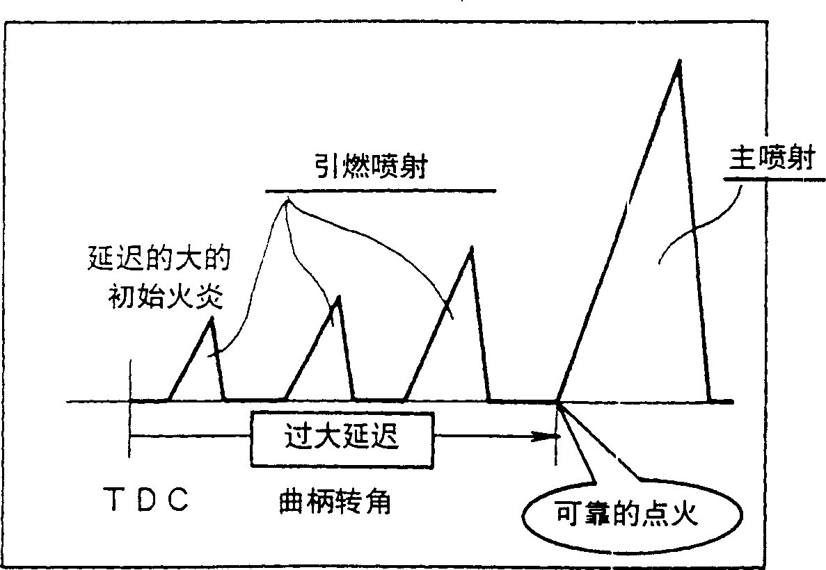
[0059] A multi-stage injection test accompanied by heating with a glow plug and a multi-stage injection test without heating with a glow plug were carried out below, and a comparative study was carried out. All the tests were three-stage multi-stage injection with pilot injection twice and main injection once.

[0060] As an example of exhaust gas temperature rise with multi-stage injection heated by the glow plug, in Figure 4 , shows the multi-stage injection in the case of heating with glow plugs at idling at an engine speed of 850 rpm. and, in Figure 5 A comparative example of exhaust gas temperature rise without concomitant heating with glow plugs is shown in .

[0061] according to Figure 4 with Figure 5 , it can be seen that the exhaust gas temperature immediately after starting, that is, the exhaust gas temperature at the turbine inlet, is greatly increased to about 500°C in the embodiment compared with about 300°C in the comparative example, and the temperature...


PUM


Abstract

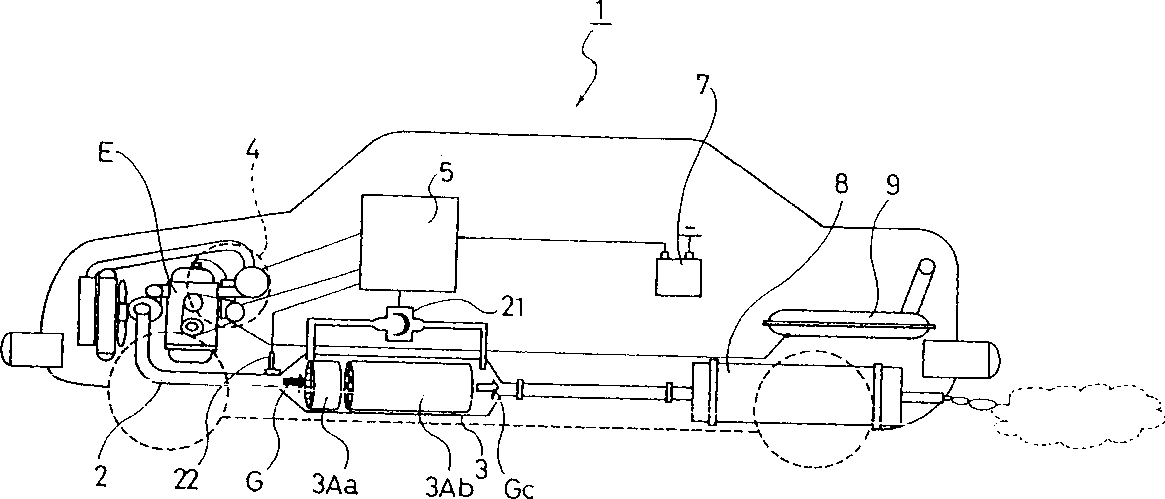
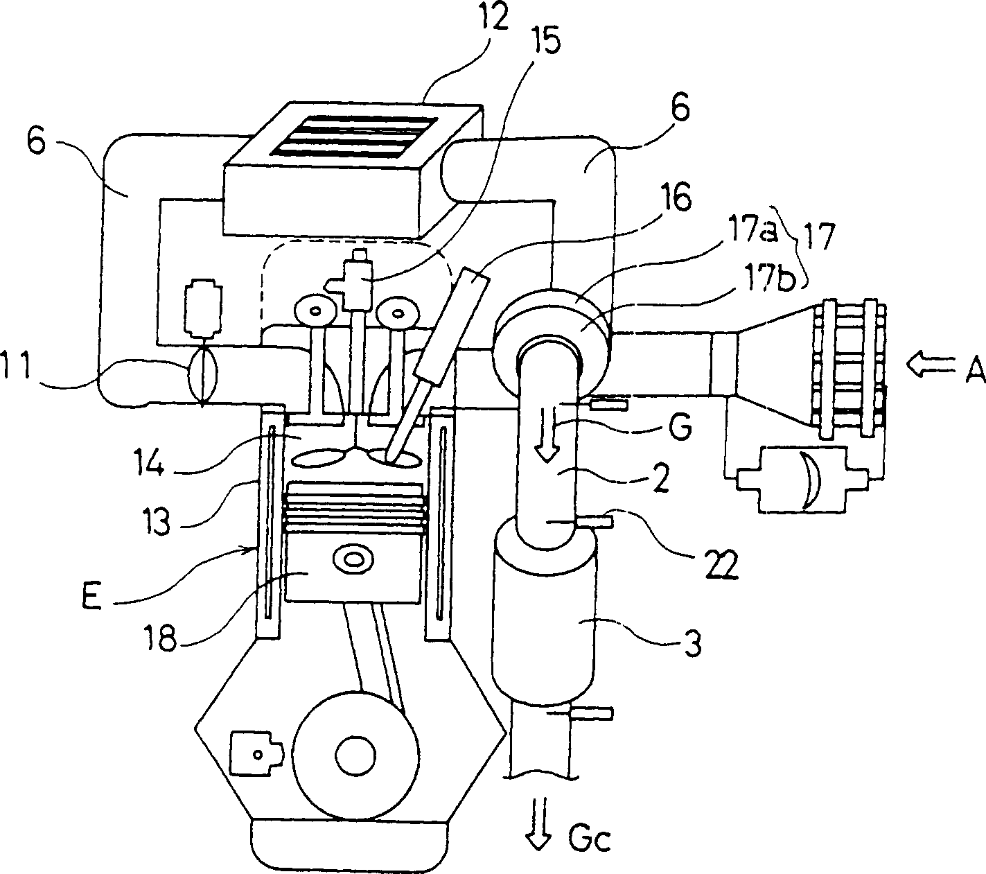
An exhaust gas purifying system (1) aving a continuous regeneration DPF (3) installed in the exhaust passage (2) of a diesel engine (E) provided with a glow plug (16) and a regeneration control means for regenerating the continuous regeneration DPF (3), is constituted so that the regeneration control means performs retarded injection or post-injection in the control of fuel injection into a cylinder (13) and heating the inside of the cylinder (13) by the glow plug (16) for regenerating the continuous regeneration DPF (3). Thereby, when raising the temperature of exhaust gas in the regeneration of the continuous regeneration DPF (3), it is possible to prevent the generation of white fumes and misfire and to raise the exhaust gas temperature efficiently and substantially. Therefore, it is possible to prevent the temperature of a catalyst and a DPF from being abnormal high and to prevent the deterioration and the melt down of the catalyst.

Description

technical field [0001] The present invention relates to an exhaust gas purification system including a continuously regenerated diesel particulate filter (Diessel Particulate Filter) (hereinafter referred to as DPF) in a diesel engine with a glow plug to purify diesel engine exhaust gas. Background technique [0002] Restrictions on the emission of fine particulate matter (hereinafter referred to as PM) from diesel engines, and the emission of NOx, CO, HC, etc. are becoming stricter every year. Therefore, with the increasing restrictions, the improvement of the engine alone cannot meet the needs. Therefore, a technology has been developed that uses a filter called a DPF to capture PM emitted by the engine and reduce the amount of PM emitted to the outside. [0003] The DPF that directly captures this PM includes a single-cell honeycomb wall-flow filter made of ceramics, and a fiber-type filter made of ceramics and metals into fibers. The exhaust gas purification system usi...

Claims


Application Information

Patent Timeline
Patent Type & Authority Applications(China)
IPC IPC(8): B01D53/94F01N3/02F01N3/023F01N3/035F01N3/20F01N3/24F01N9/00F01N13/02F02B23/02F02B37/00F02D41/02F02D41/04F02D41/38F02D41/40F02D43/00F02P5/15F02P19/02
CPCF01N13/009F01N2230/02F01N13/02F01N2013/026F01N2430/08F02B37/00F02D41/405F01N2230/04F01N9/002F01N3/204F01N3/0231Y02T10/44F02D41/403F02D41/029F02P5/1516Y02T10/26Y02T10/47F01N3/035F02P19/026B01D53/9495F01N13/0097Y02T10/12Y02T10/40
Inventor 我部正志田代欣久
Owner ISUZU MOTORS LTD
Learn More