
Method for processing hidh-precision sub-photoetched pattern on substrate

A sub-lithography, high-density technology, applied in the field of processing high-density sub-lithography patterns, can solve problems such as density increase

Inactive Publication Date: 2003-11-12
HEWLETT PACKARD CO
View PDF0 Cites 3 Cited by
  • Summary
  • Abstract
  • Description
  • Claims
  • Application Information

AI Technical Summary

Problems solved by technology

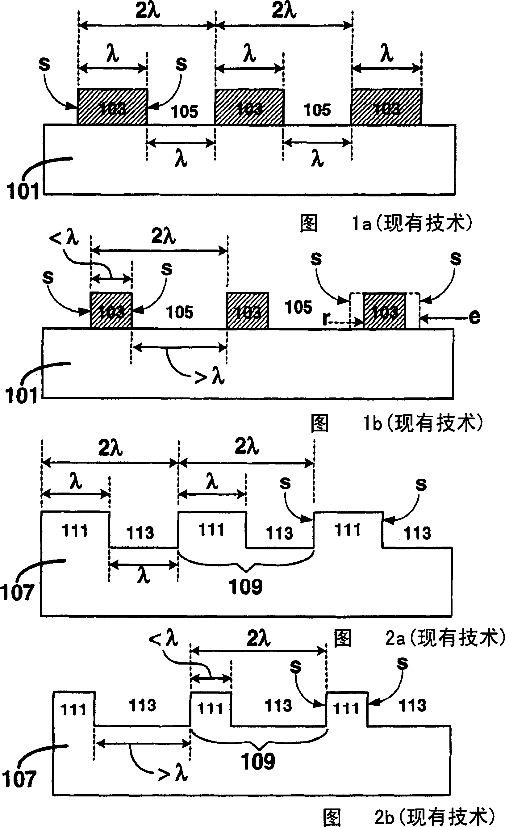
However, the above method does not increase the density of the lines 103

Method used


Image

  • Method for processing hidh-precision sub-photoetched pattern on substrate
  • Method for processing hidh-precision sub-photoetched pattern on substrate
  • Method for processing hidh-precision sub-photoetched pattern on substrate

Examples


Embodiment Construction

[0030] In the following detailed description and some of the drawings, similar elements are identified with similar reference numerals.

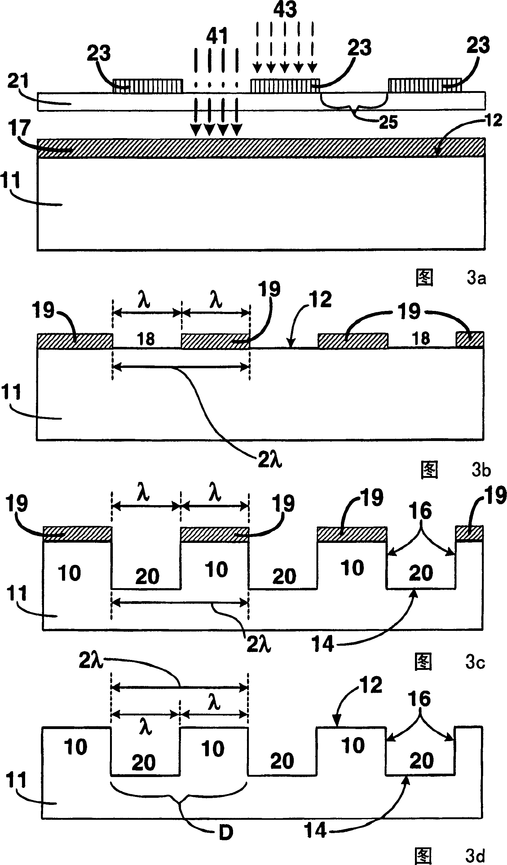
[0031] As shown in the illustrative figures, the present invention is embodied in a method of fabricating high density sublithographic patterns. The method involves depositing a masking layer on a substrate and then patterning the masking layer to form an image comprising a feature size that is larger than the photolithography used to pattern the masking layer. The minimum resolution of the system is greater or equal. The masking layer is then etched to transfer the image onto the substrate, thereby defining features on the substrate. This graph includes the minimum feature size, as well as horizontal and vertical sidewall surfaces.

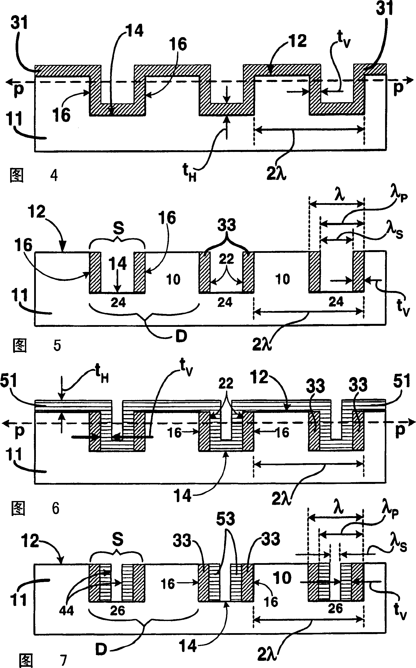
[0032] Spacer material is deposited over the features to cover the horizontal surfaces and vertical sidewall surfaces. The deposition process continues until the spacer material has a predetermined thickness...


PUM


Abstract

A method of fabricating high density sub-lithographic features is disclosed. The method includes the use of common microelectronic processes including sub-lithographic spacer formation and Damascene processes to form a plurality of sub-lithographic spacers on vertical side wall surfaces of features carried by a substrate. The sub-lithographic spacers have a period that is less than a minimum resolution of a lithographic system. The density of features, including the sub-lithographic spacers, within a minimum resolution of the lithographic system, can be increased by subsequent depositions of material, followed by anisotropic etching to selectively remove horizontal surfaces of the deposited material. Optionally, the spacer materials can be conformally deposited.

Description

technical field [0001] The present invention generally relates to methods of fabricating high density sublithographic patterns on substrates. More specifically, the present invention relates to a method for processing high-density sublithographic patterns on a substrate using common microelectronic processing techniques, so that some sublithographic intervals are formed on the substrate, and within the range of the minimum resolution of the lithographic system The inner feature density can be doubled or more. Background technique [0002] In the microelectronics industry, the standard method of patterning features on a substrate is by the well-known photolithographic technique. Usually a layer of photoresist is coated on the substrate material first, and then a light source is used to expose the photoresist through a mask. The mask contains patterns (such as lines and spaces) that will be transferred to the photoresist. After exposure the photoresist is soaked in a soluti...

Claims


Application Information

Patent Timeline
IPC IPC(8): G03F7/20G03F7/00H01L21/027H01L21/033H01L21/306H01L21/3065H01L21/308H01L21/311
CPCG03F7/0005B82Y10/00B82Y40/00G03F7/0002H01L21/0337H01L21/027
Inventor T·安东尼
Owner HEWLETT PACKARD CO
Learn More