
Internal combustion steam thermal engine

A heat engine, internal combustion steam technology, applied in the direction of engine components, machines/engines, mechanical equipment, etc., can solve the problems of not considering the fuel ignition conditions, service life, unburned, etc., to reduce rough combustion or The effect of knocking phenomenon, improving low temperature starting ability, and sufficient fuel combustion

Inactive Publication Date: 2003-03-26
赵晶
View PDF0 Cites 17 Cited by
  • Summary
  • Abstract
  • Description
  • Claims
  • Application Information

AI Technical Summary

Problems solved by technology

[0004] (1) The cooling device is not removed and the heat preservation device is not installed, so the recovery rate of the heat energy lost by the original internal combustion engine is not high;
[0005] (2) The automatic adjustment and control device and automatic fault protection and alarm device are not installed, so the engine cannot work normally and smoothly;
[0006] (3) It did not take into account that the ignition conditions of the fuel could be improved by changing the fuel temperature, so that the fuel combustion of the engine would be more complete, and the low-temperature start of the engine would be easier;
[0008] (5) How to adapt a lubricating oil to various temperatures and prolong its service life is not considered;
[0009] (6) How to prevent the formation of nitrogen oxides is not considered;
[0010] (7) No consideration is given to how to solve the problem that some fuel is directly discharged without burning when the piston-type two-stroke ignition internal combustion engine is working;
[0011] (8) The idea of ​​using water to decompose and fission (hydrogen and oxygen) after heating to save energy by 20% does not conform to the law of energy conversion and conservation, it belongs to the principle of perpetual motion machine, and violates the relevant provisions of patent application and approval

Method used


Image

  • Internal combustion steam thermal engine
  • Internal combustion steam thermal engine
  • Internal combustion steam thermal engine

Examples


Embodiment Construction

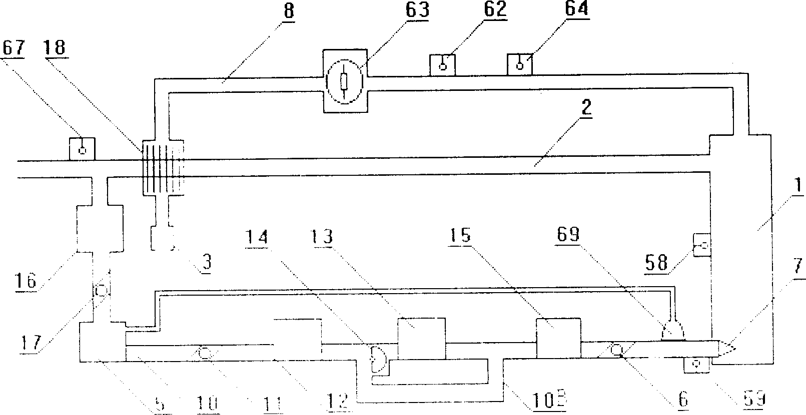
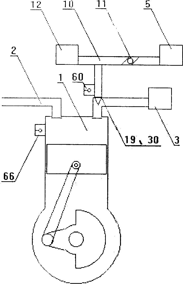
[0035] Depend on figure 1 It can be seen that the internal combustion steam engine of the present invention is based on the existing engine main body (not drawing power output parts such as pistons, rotors, gas wheels, etc.) generated by the expansion of high-temperature exhaust gas after fuel combustion, except retaining the original Combustion chamber 1 on the engine, exhaust pipe (or exhaust port) 2, air (oxygen) gas source (or air filter) 3, fuel source 4 and other components, and remove various parts for heat dissipation, and then Install water storage tank 5, high-pressure water pump 6 and install high-pressure sprinkler 7 to form on combustion chamber. The high-pressure water injector 7 is installed in the position that the water of spraying both does not affect the normal combustion of the fuel in the combustion chamber 1, and can make the water of spraying absorb the heat energy that the fuel combustion produces rapidly and gasify instantly. When the engine is workin...


PUM


Abstract

The invention relates to an internal combustion steam engine that is based on the internal combustion thermodynamic generator. The variable radiators are taken out from the traditional engine, while the warm keep cover, and heat absorbing water spray system formed by water tank, low pressure water pump, water cooling heat exchanger, high pressure pump, high water sprayer, are installed on the outside of traditional engine and connected through the water delivery pipe according to the above order, thereof, the high pressure water sprayer if installed on the high temperature part of the firebox; besides, by reforming the fuel atomization and spraying device onto the air-changing channel to make engine save energy and the more environment-protective.

Description

technical field [0001] The invention relates to an energy-saving and environment-friendly internal combustion steam heat engine using water as a heat conversion agent and an antiknock agent. Background technique [0002] The thermal engine in the prior art, although its working principle is to utilize the fuel combustion to make the working medium thermally expand to generate power, but due to its working principle and the imperfection of its own design, some heat energy generated when the fuel must be burned must be dissipated and Only when it is wasted can it work normally. For example, piston internal combustion engines and gas turbines must be cooled when they work, and the exhaust gas contains a lot of heat energy, so the thermal efficiency is generally low, of which 6-15% for steam engines, 25-30% for steam turbines, and piston ignition Internal combustion engine (gasoline engine) 20~30%, piston compression ignition internal combustion engine (diesel engine) 28~40%, ga...

Claims


Application Information

Patent Timeline
Patent Type & Authority Applications(China)
IPC IPC(8): F02M25/03
Inventor 赵晶
Owner 赵晶
Learn More