Glass melting crucible furnace with dual flow directions
A glass crucible and double-flow technology, which is applied in the field of crucible furnaces, can solve the problems of abnormal melting material liquid, affecting normal production, and inability to guarantee material quality, and achieve the effects of simple structure, improved service life, and stable furnace temperature
- Summary
- Abstract
- Description
- Claims
- Application Information
AI Technical Summary
Problems solved by technology
Method used
Image

Examples
Embodiment 1
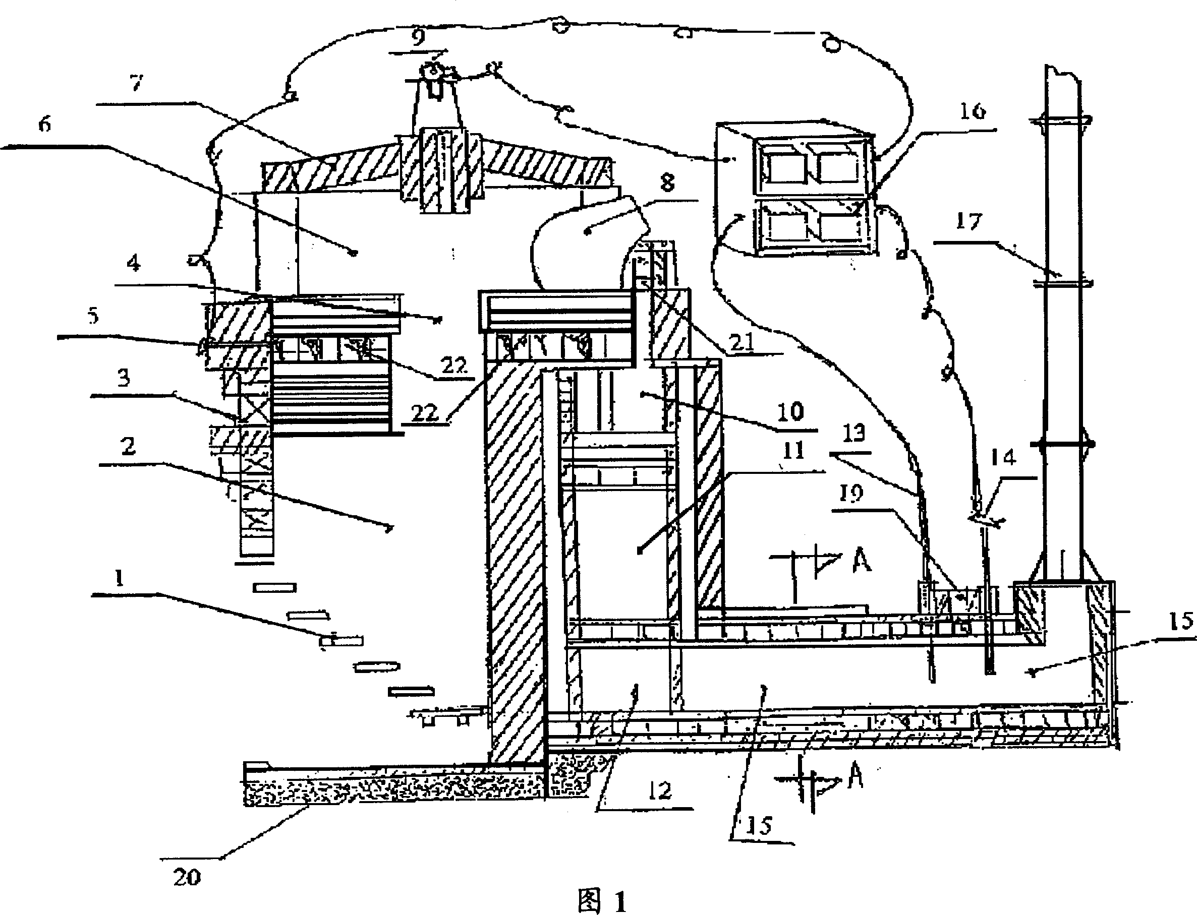
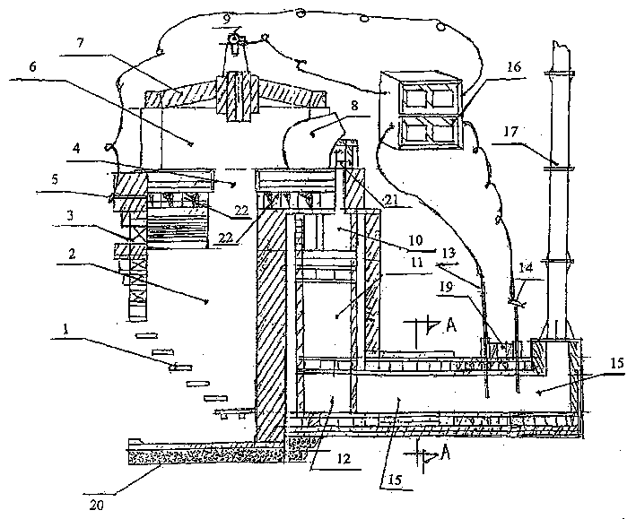
[0026] A third layer of flue (12) is arranged on one side of the furnace foundation (20) top of the body of furnace, and a second layer of flue (11) is arranged on the top of the third layer of flue (12), and the third layer of flue (12) is connected to the The second layer of flue (11) is connected, the upper part of the second layer of flue (11) is provided with the first layer of flue (10), the second layer of flue (11) is connected with the first layer of flue (10) A small chimney (21) is set on one side of the top of the first layer of flue (10), and the small chimney (21) is connected with the first layer of flue, and several air storage chambers are set on one side of the small chimney (21) ( 22), the upper part of the air storage chamber (22) is provided with several crucibles (8). One end of the flue heat displacer (18) is connected with one side of the third-layer flue (12), and the other end of the flue heat displacer (18) is connected with the lower end of the chim...
Embodiment 2
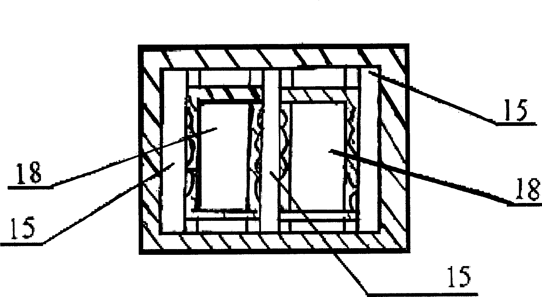
[0033] Inside the heat displacer (15), two flue heat displacers (18) are relatively parallelly arranged along the heat displacer (15), and the two flue heat displacers (18) are arranged relatively parallel to each other.
[0034] One end of the heat exchanger (15) is connected to one side of the third layer flue (12), and passes through the second layer flue (11) and the first layer flue (10) and the air storage chamber (22) Connected, the other end of heat exchanger (15) is connected with one end of air inlet (19) and chimney (17).
[0035] The upper part of the other end of the heat displacer (15) is provided with a chimney suction force detector (13), a flue side temperature instrument (14) and an air inlet (19), a chimney suction force detector (13) and a flue side Thermometer (14) is connected with instrument control box (16).
[0036]The secondary air enters the heat displacer (15) from the air inlet (19) and performs heat displacement with the flue heat displacer (18)....
Embodiment 3
[0038] The heat energy generated by the furnace (2) is converted into hot air and then enters the melting chamber (6) to heat and melt the glass material liquid in the crucible (8). After heating, part of the waste gas passes through the small chimney (21), the first layer of flue (10 ), the second layer of flue (11), the third layer of flue (12) and the flue heat displacer (18), exhaust gas is removed by the chimney (17); the secondary air enters the heat from the air inlet (19) The displacer (15) performs heat displacement with the flue heat displacer (18), and the secondary air rotates along the heat displacer (15) and passes through the third layer of flue (12), the second layer The flue (11) and the first layer of flue (10) enter the air storage chamber (22), and the heat-displaced secondary air enters the pre-combustion burner (4) from the air storage chamber (22) and mixes and burns with the coal gas to improve The temperature of melting chamber (6) reciprocates, as sho...
PUM
| Property | Measurement | Unit |
|---|---|---|
| heating value | aaaaa | aaaaa |
Abstract
Description
Claims
Application Information
 - Generate Ideas
- Intellectual Property
- Life Sciences
- Materials
- Tech Scout
- Unparalleled Data Quality
- Higher Quality Content
- 60% Fewer Hallucinations
Browse by: Latest US Patents, China's latest patents, Technical Efficacy Thesaurus, Application Domain, Technology Topic, Popular Technical Reports.
© 2025 PatSnap. All rights reserved.Legal|Privacy policy|Modern Slavery Act Transparency Statement|Sitemap|About US| Contact US: help@patsnap.com