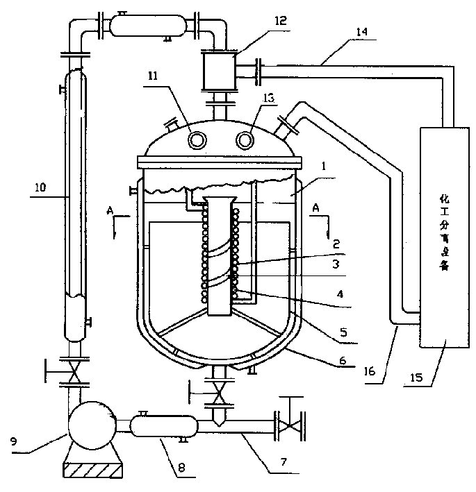
Coupling equipment of reaction and separation
A coupling device and reaction technology, applied in chemical/physical/physicochemical processes, chemical instruments and methods, chemical/physical processes, etc., can solve problems that are difficult to achieve, heat transfer, mass transfer and mixing efficiency are not high, and cannot be performed, etc. problems, to achieve the effect of reducing side reaction products, waste discharge, clean production, and reducing waste generation
- Summary
- Abstract
- Description
- Claims
- Application Information
AI Technical Summary
Problems solved by technology
Method used
Image
Examples
example 1
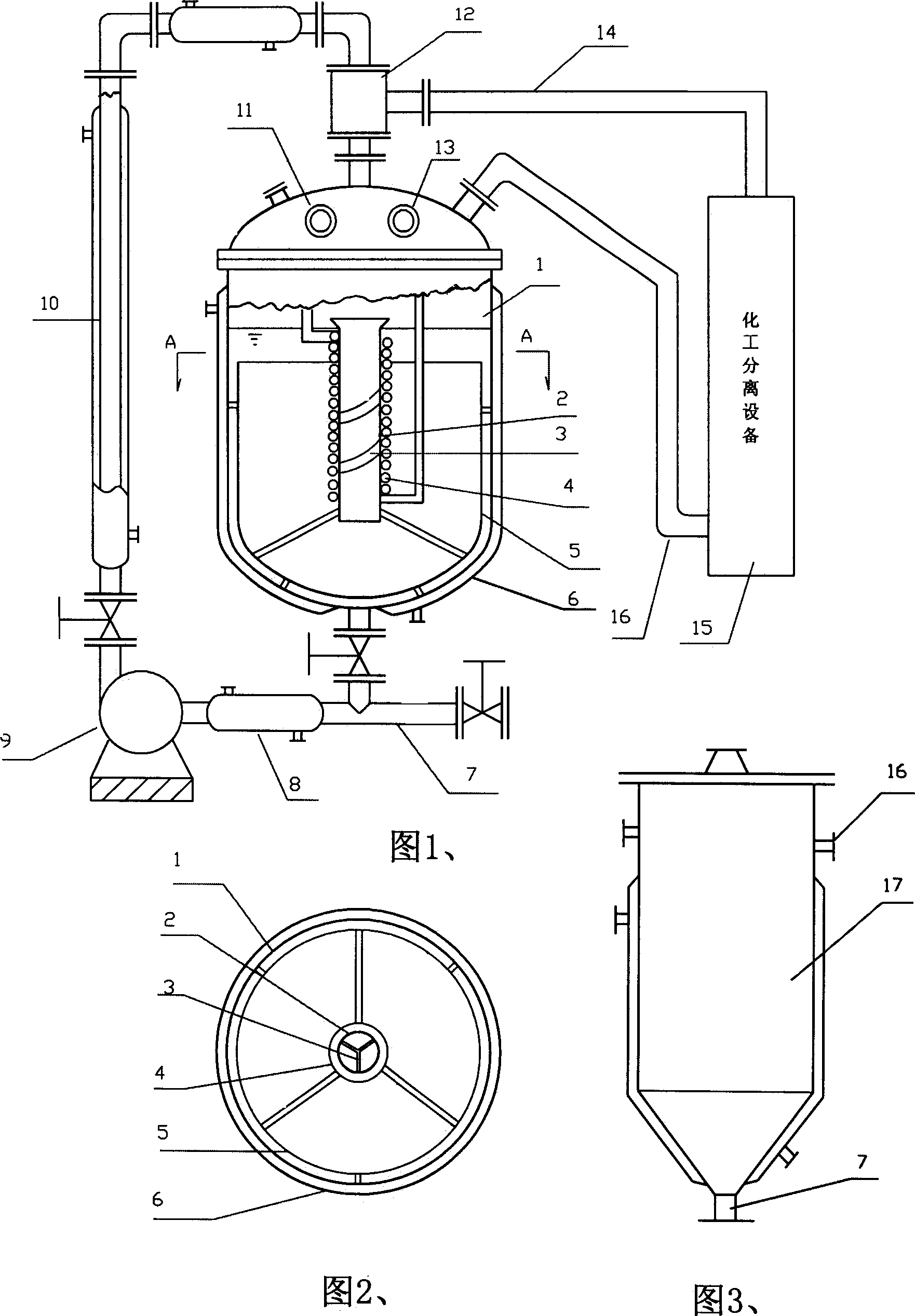
[0018] Example 1. Apparatus for chemical reaction (1):
[0019] aA (l) +bB (l) =cC (l) +dD (g) ……(1)
[0020] In the formula: A and B are reactants (liquid under reaction temperature and pressure),
[0021] C is the reaction main product (liquid under reaction temperature and pressure),
[0022] D is reaction by-product (gas under reaction temperature, pressure, as HCl, NO 2 、H 2 S, HF, NH 3 Wait).
[0023] The device shown in Fig. 1 is designed for chemical reaction (1), and it comprises reactor and the circulation pump 9 that is connected with it, sparger 12 and as the liquid phase circulation pipeline of chemical reaction circulation and its filling with fixed bed The catalyst column also includes a gas phase circulation pipeline as a separation cycle, and the gas phase circulation pipeline is connected to the chemical separation equipment 15 and the reactor through the gas phase circulation ejector inlet pipe 14 and the gas phase circulation separa...
example 2
[0027] Example 2. Apparatus for chemical reaction (2):
[0028] aA (l) +bB (l) =cC (l) +dD (l) …….(2)
[0029] In the formula: A, B, C, and D are all liquids under the reaction conditions, but A or B is in a saturated liquid state.
[0030] A, B, and D are more volatile than C.
[0031] C is the main product and D is the by-product (H 2 O, CH 3 OH, CH 3 CH 2 OH, etc.) can be volatile to gas at operating temperature.
[0032] This device is similar to example 1 device, and difference is: just chemical separation equipment 15 changes rectifying tower into. Reactor 1 is the main reaction area, on which there is a heating jacket 6, and a heat exchange jacket 8 is also arranged on the liquid circulation pipe. If the heat transfer surface is not enough, the liquid circulation pipe can be changed into two or more pipes in parallel for use. To increase the heat transfer area to facilitate heating or remove heat.
[0033]The reactants are heated to a certain...
example 3
[0035] Example 3. Apparatus for chemical reaction (3):
[0036] aA (G) +bB (L) cC (l) +dD (G) ...(3)
[0037] In the formula: under reaction condition, reactant A is gas (such as H 2 、HN 3 、CI 2 , CO, etc.),
[0038] Reactant B is a liquid;
[0039] The main product C is liquid;
[0040] The by-product D is gas (can be separated by acid or lye or adsorbent);
[0041] The catalyst for the reaction is a homogeneous or fixed-bed catalyst.
[0042] The difference of this device and example 1 device is: just reactor is a volume and cylinder diameter less reaction tower 17 (Fig. 3), therefore, the residence time of gas-liquid mixture in tower is shorter, the time of gas-liquid separation It is also shorter, so that the gas holdup in the liquid phase entering the liquid phase circulation pipe remains high. The injector is arranged at the top of this column. The circulation pump can be an axial flow pump, or a centrif...
PUM
 Abstract
Description
Claims
Application Information
 - R&D
- Intellectual Property
- Life Sciences
- Materials
- Tech Scout
- Unparalleled Data Quality
- Higher Quality Content
- 60% Fewer Hallucinations
Browse by: Latest US Patents, China's latest patents, Technical Efficacy Thesaurus, Application Domain, Technology Topic, Popular Technical Reports.
© 2025 PatSnap. All rights reserved.Legal|Privacy policy|Modern Slavery Act Transparency Statement|Sitemap|About US| Contact US: help@patsnap.com


