Fuel cell
A fuel cell and fuel technology, applied in the direction of fuel cells, fuel cell components, solid electrolyte fuel cells, etc., can solve the problem of less expensive batteries and achieve low cost effects
- Summary
- Abstract
- Description
- Claims
- Application Information
AI Technical Summary
Problems solved by technology
Method used
Image
Examples
example 1
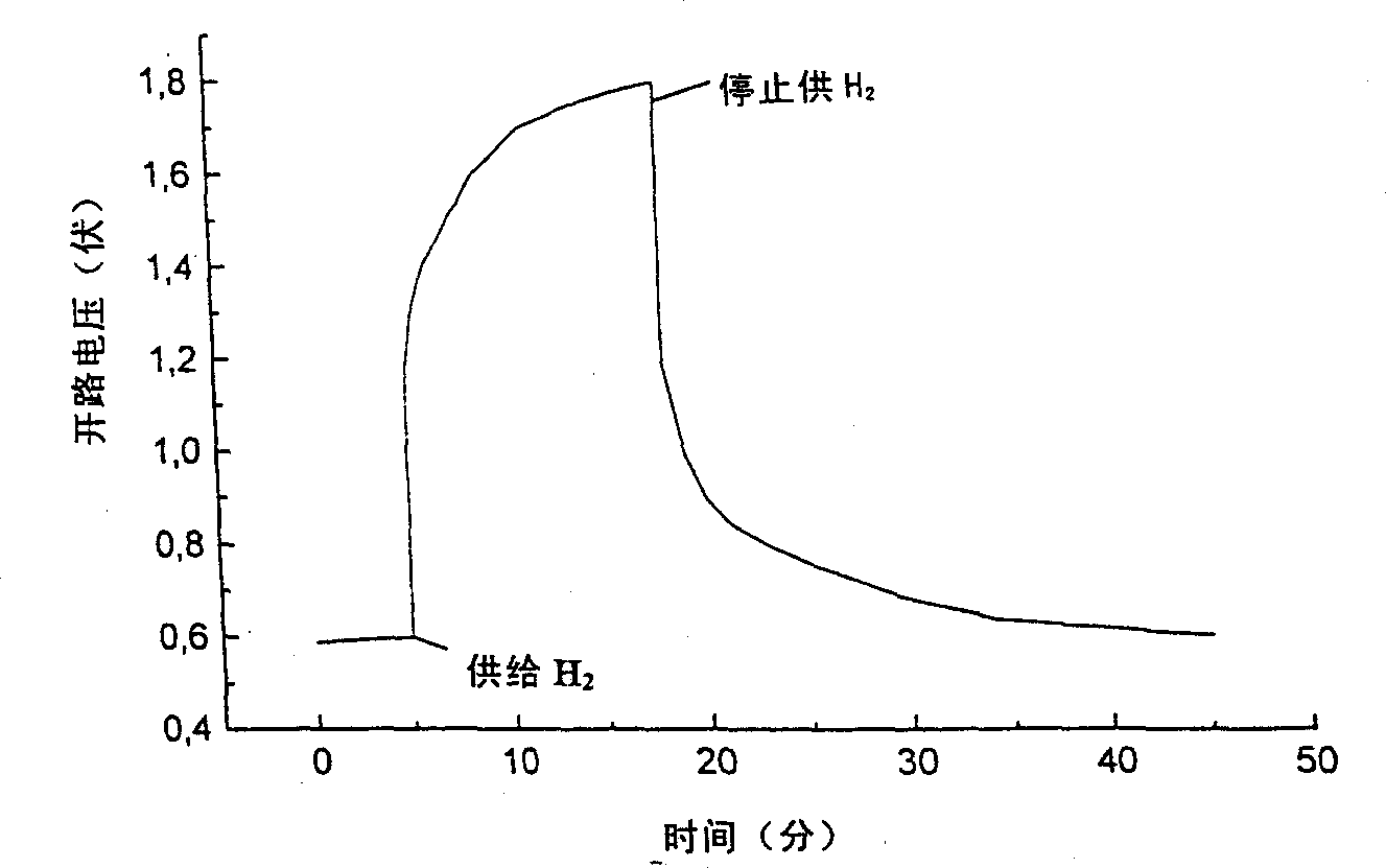
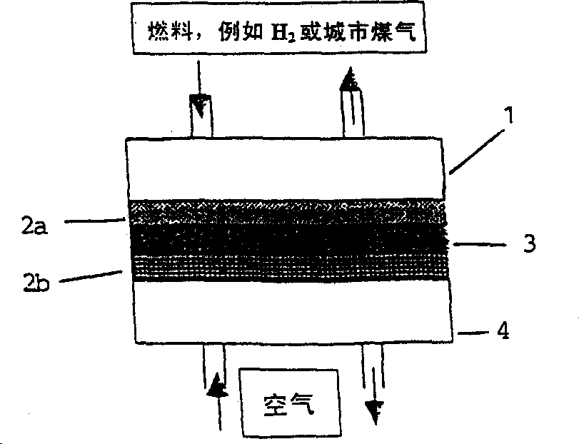
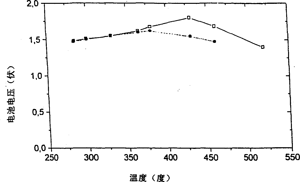
[0079] In ambient atmosphere, according to the present invention figure 1 The device shown shows an OCV between 0.4 and 0.6V. The current that can be drawn for both electrodes drops rapidly. As long as doped NiO x With hydrogen supplied to the anode and air supplied to the LaSrCoFeO cathode, the OCV rises immediately to about 1.0 V and gradually increases to about 1.5 to 1.8 V over time. When the hydrogen supply was stopped, the OCV first dropped sharply and then gradually decreased with time. These observations indicate that figure 2 . By exchanging the electrode terminals, i.e., hydrogen to LaSrCoFeO, air to doped NiO x Electrodes are supplied to complete further tests. At this time, the device shows an OCV close to the former OCV value but negative (ie opposite sign to the former).
[0080] image 3 Two curves are shown for devices of the invention using different salt electrolytes. Dozens to hundreds of mA / cm 2 can be obtained from this device. A typical curre...
example 2
[0081] Example 2 (electrodeless configuration)
[0082] When using only Gd x Ce 1-x Using an electrolyte instead of electrodes to construct a fuel cell device, the OCV of this 'electrodeless configuration' fuel cell device is 0.96V, which is about 0.2V higher than a conventional device with electrodes and the same electrolyte configuration. But only about 2mA / cm is obtained from the device 2 . This function is based on the ion-conducting Gd x Ce 1-xThe bulk material is an electrolyte that, when reacted with a gas, can cause significant electronic and ionic conduction on each of its surfaces and function as an anode and a cathode, respectively. The performance of the device was found to be limited by the air surface because at the air (or oxygen) end Gd x Ce 1-x Cannot cause sufficient electronic conduction, forming an improved configuration that uses only one electrode such as Pt or Ag (slurry) as the cathode, namely:
[0083] (H 2 )Gd x Ce 1-x / Pt or Ag(air)
[00...
example 3
[0085] Example 3 (utility device)
[0086] Fuel cells using fluoride- and hydrofluoride-based composite electrolytes (proton-conducting type) and cerium oxide-salt (halide) composite electrolytes are typical examples of practical ITCFC devices. Figure 5 An example is shown. All of these new ITCFCs have demonstrated performance well up to current commercial standards. In addition, ITCFCs use sulfate-based electrolytes as highly sulfur-tolerant devices capable of processing fuels with high sulfur content, such as natural gas or by-products from petroleum refining processes, while generating electricity. This sulfur-resistant CFC device is expected to be used as a gas pretreatment station, combined with MCFC power plants to create a new power generation technology.
PUM
| Property | Measurement | Unit |
|---|---|---|
| current density | aaaaa | aaaaa |
| current density | aaaaa | aaaaa |
Abstract
Description
Claims
Application Information
 - R&D Engineer
- R&D Manager
- IP Professional
- Industry Leading Data Capabilities
- Powerful AI technology
- Patent DNA Extraction
Browse by: Latest US Patents, China's latest patents, Technical Efficacy Thesaurus, Application Domain, Technology Topic, Popular Technical Reports.
© 2024 PatSnap. All rights reserved.Legal|Privacy policy|Modern Slavery Act Transparency Statement|Sitemap|About US| Contact US: help@patsnap.com


