
Tubular, hollow and steel bar reinforced concrete floor member

A technology for reinforced concrete tubular and hollow-core slabs, which is applied to floors, building components, buildings, etc., and can solve problems such as the inability to form two-way reinforced concrete tubular hollow-core slabs with well-shaped ribs, large differences in two-way rigidity, and large thickness of hollow-core slabs. Lightweight, small difference in two-way force transmission, and small deflection deformation

Inactive Publication Date: 2004-09-01
邱则有
View PDF0 Cites 0 Cited by
  • Summary
  • Abstract
  • Description
  • Claims
  • Application Information

AI Technical Summary

Problems solved by technology

Since the concrete in the slab is evacuated by the hollow tube member, there are longitudinal ribs of cast-in-place reinforced concrete longitudinally along the outer side of the tube, while there are no force-transmitting members in the transverse direction, or only two ribs to prevent the entry of wet concrete or cement slurry. Sealing and plugging make the existing hollow floor slab unable to bear complex tension, pressure, shear force, punching force, torque, etc. in the horizontal direction, so that the rigidity of the cast-in-place reinforced concrete tubular hollow floor slab is greatly different in two directions, and it is impossible to form a well. Two-way reinforced concrete tubular hollow floor slab equivalent to word rib
Compared with the double-ribbed slab floor, this kind of hollow slab has a large thickness of the hollow slab, large consumption of reinforced concrete, heavy weight, large deflection and deformation, poor shear and torsion resistance, and cast-in-place concrete on the upper and lower flanges of the hollow tube. The weak points are prone to cracks, poor seismic performance, large difference in two-way rigidity, easy damage to pipes, large leakage of cast-in-place concrete, and high cost

Method used


Image

  • Tubular, hollow and steel bar reinforced concrete floor member
  • Tubular, hollow and steel bar reinforced concrete floor member
  • Tubular, hollow and steel bar reinforced concrete floor member

Examples


Embodiment Construction

[0070] The present invention will be further described below in conjunction with the accompanying drawings and embodiments.

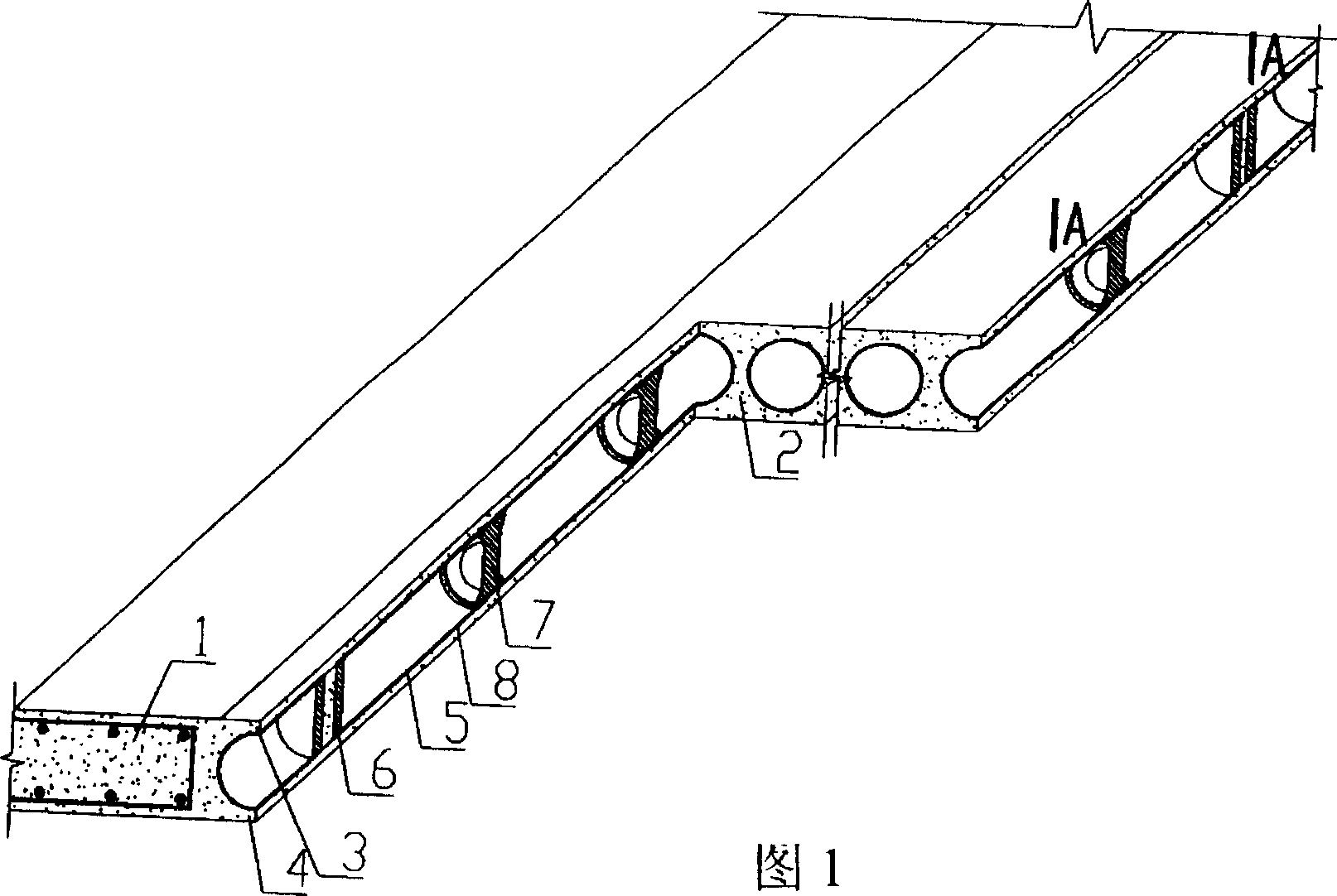
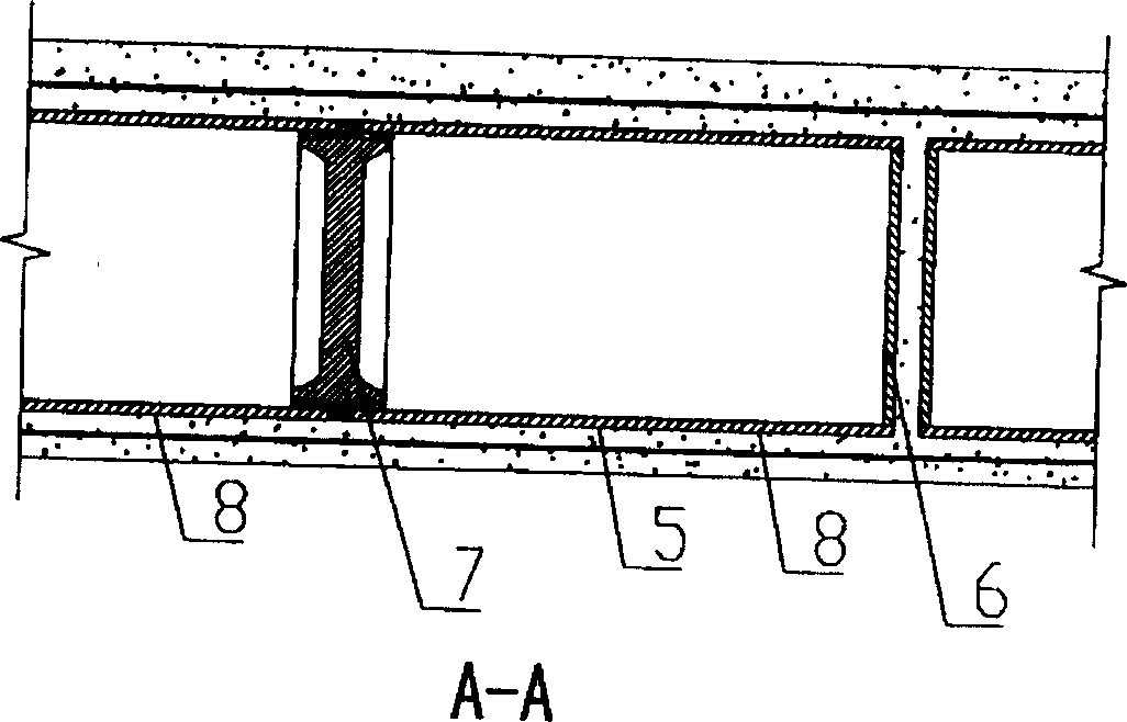
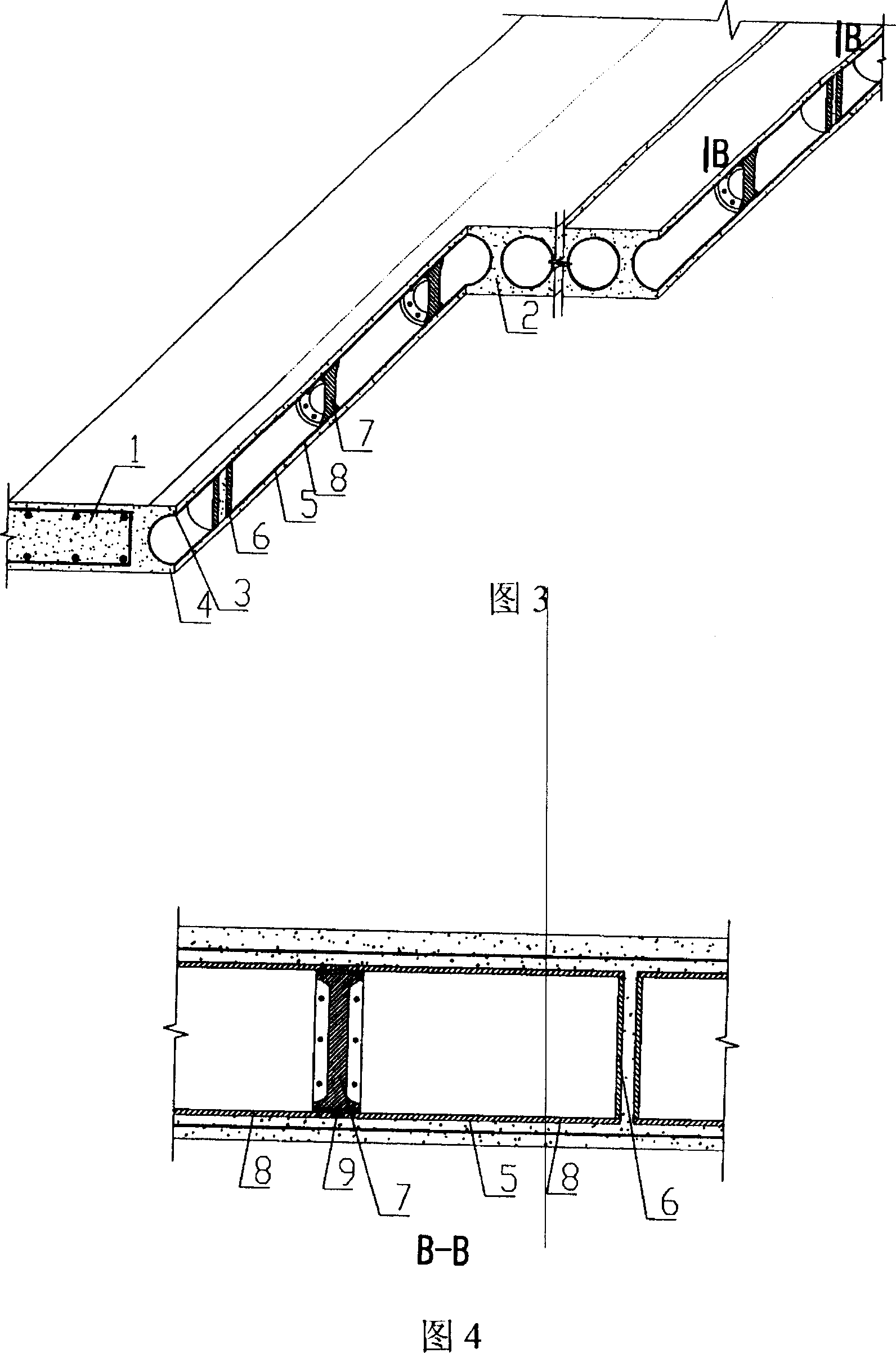
[0071] As shown in the accompanying drawings, the present invention includes beams between wall columns 1, cast-in-place reinforced concrete longitudinal ribs 2, cast-in-place reinforced concrete upper wing plates 3, cast-in-place reinforced concrete lower wing plates 4, hollow tubes 5, and the hollow tubes 5 are arranged alternately Between the cast-in-place reinforced concrete longitudinal ribs 2 or the beams between wall columns 1, above it is the cast-in-place reinforced concrete upper wing 3, below it is the cast-in-situ reinforced concrete lower wing 4, and there are plugs 6 at both ends of the hollow pipe 5 , characterized in that the hollow tube 5 is a combined hollow tube, the combined hollow tube 5 is composed of more than two hollow tube units 8, and the two hollow tube units 8 are butted at the stiffener 7. Fig. 1 shows that the combined hol...


PUM


Abstract

A reinforced concrete tubular hollow floor slab includes beam between wall and column, cast-in-situ RC longitudinal rib, cast-in-situ RC upper flange, cast-in-situ RC lower flange and hotlow tube; the hollow tube is arrnaged alternate with each other between cast-in-situ RC longitudinal ribs or between beams between wall and column, cast-in-situ RC upper flange is at its top, cast-in-situ RC lower flange at its bollom, the hollow-tube has plugs at toth ends, and it is characterized by that the hollow tube is a composite one containing at least one stiffening rib and at least over two seetions of hollow tubes which are butt-jointed for connection at stiffeing rit, and the stiffening rib is combined with cast-in-situ RC longitudinal rib to constitute two-way hidden dense rib structure.

Description

(1) Technical field [0001] The invention relates to a reinforced concrete tubular hollow floor slab. (2) Background technology [0002] At present, in the prior art, the hollow tube components are generally paper tubes, plastic tubes, metal bellows or hollow hard thin-walled components. These hollow tube components are mainly considered to evacuate the concrete to reduce the weight of the floor slab. The existing reinforced concrete tubular hollow floor slabs include beams between wall columns, cast-in-place reinforced concrete longitudinal ribs, cast-in-place reinforced concrete upper flanges, cast-in-situ reinforced concrete lower flanges, and hollow tubes. Between longitudinal ribs or beams between wall columns, above it is the cast-in-place reinforced concrete upper wing, below it is the cast-in-place reinforced concrete lower wing, and there are plugs at both ends of the hollow tube, and the cross-sectional shape of the hollow tube member can be circular , square or ot...

Claims


Application Information

Patent Timeline
Patent Type & Authority Patents(China)
IPC IPC(8): E04B5/18E04B5/32E04B5/36
Inventor 邱则有
Owner 邱则有
Learn More