
Deposition device for densification of prefabricated body and charging structure

A deposition device and preform technology, applied in metal material coating process, coating, gaseous chemical plating and other directions, can solve the problem that it cannot be used for the preparation of thick-walled parts, the density of the parts is uneven, and the surface of the parts is easy to crust. and other problems to achieve the effect of avoiding surface crusting, uniform densification density, and increasing the probability of collision

Pending Publication Date: 2022-08-09
BAOSHAN LONGI SILICON MATERIALS CO LTD
View PDF0 Cites 0 Cited by
  • Summary
  • Abstract
  • Description
  • Claims
  • Application Information

AI Technical Summary

Problems solved by technology

Although this process can avoid damage to fibers and matrix, improve the microstructure of matrix, and improve the performance of composite materials, there are still many shortcomings, such as long deposition period, uneven density of parts, and cannot be used to prepare thick walls. Parts, and the surface of the workpiece is easy to crust during the deposition process, and it is necessary to continuously use mechanical processing methods to cut the shell

Method used


Image

  • Deposition device for densification of prefabricated body and charging structure
  • Deposition device for densification of prefabricated body and charging structure

Examples


Embodiment Construction

[0022] The present application will be further described in detail below with reference to the accompanying drawings and embodiments. It should be understood that the specific embodiments described herein are only used to explain the related invention, rather than limit the invention. In addition, it should be noted that, for the convenience of description, only the parts related to the invention are shown in the drawings.

[0023] It should be noted that the embodiments in the present application and the features of the embodiments may be combined with each other in the case of no conflict. The present application will be described in detail below with reference to the accompanying drawings and in conjunction with the embodiments.

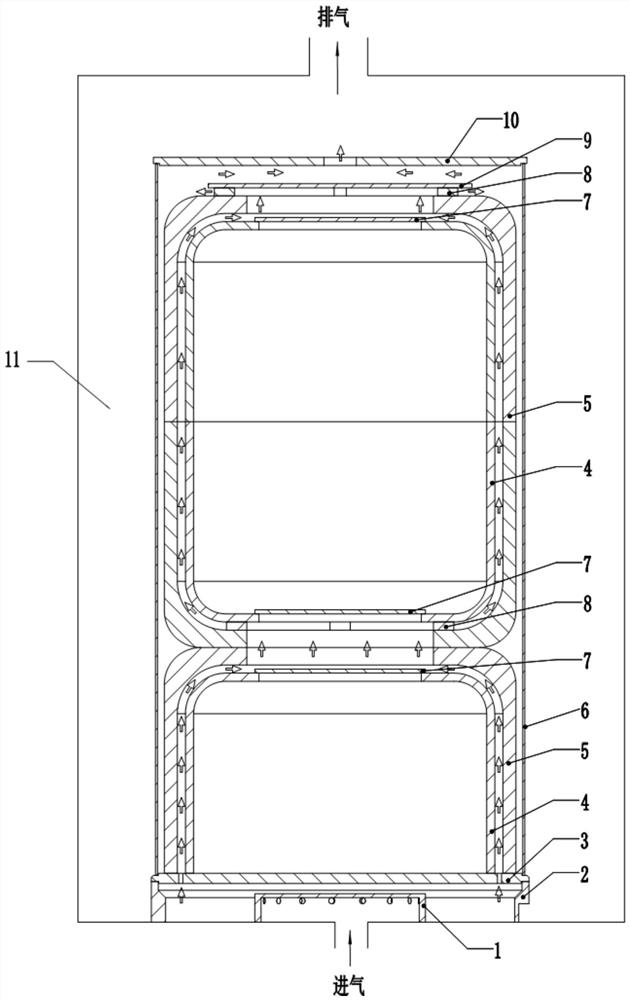
[0024] figure 1 and figure 2 A schematic diagram of the deposition apparatus for preform densification provided by the embodiments of the present application is shown.

[0025] like figure 1 As shown, the deposition device for preform densif...


PUM


Abstract

The invention relates to the technical field of chemical vapor infiltration of carbon-carbon composite materials, and discloses a deposition device for densification of a preform and a charging structure. A flow limiting channel is formed between the preform to be densified and the side wall of an inner flow limiting cylinder, and an overflowing opening is formed in the top of the preform to be densified; and a flow limiting path which sequentially leads to the flow limiting channel, the overflowing opening and the furnace cavity outlet from the furnace cavity inlet is formed in the furnace cavity. In the deposition process, the temperature of a thermal field in a furnace chamber is gradually reduced from outside to inside, the deposition speed is increased exponentially along with temperature increase, carbon source gas permeates from the inner surface to the outer side with the high temperature for deposition densification, the temperature in the prefabricated body to be densified is continuously increased, and the deposition surface is continuously pushed inwards during deposition; and the whole to-be-densified prefabricated body is completely deposited, so that the surface crusting of the to-be-densified prefabricated body is avoided, and the densification density of the to-be-densified prefabricated body is uniform. In addition, through the flow limiting path, the carbon source gas activity space can be effectively compressed, the active group collision probability is increased, and therefore the deposition efficiency is greatly improved.

Description

technical field [0001] The invention generally relates to the technical field of chemical vapor infiltration of carbon-carbon composite materials, and in particular relates to a deposition device and a furnace loading structure for densification of preforms. Background technique [0002] Carbon-carbon composite materials, that is, composite materials composed of carbon fiber reinforced carbon matrix, not only have good structural properties such as high specific strength, but also have excellent functional properties such as heat resistance, thermal insulation, adsorption, superconductivity, wear resistance, etc. At present, the preparation of carbon-carbon composite materials at home and abroad generally adopts the chemical vapor infiltration process (CVI). The pyrolytic carbon is obtained by deposition, so that the carbon fiber preform is continuously densified, and finally a carbon-carbon product with the desired density is obtained. Although this process can avoid damag...

Claims


Application Information

Patent Timeline
IPC IPC(8): C23C16/26C23C16/455
CPCC23C16/26C23C16/455
Inventor 杨亮亮李永军杨荣清霍红星
Owner BAOSHAN LONGI SILICON MATERIALS CO LTD
Learn More