Conical concentric-square-shaped labyrinth structure supporting structure

A structural support and tapered technology, applied in gas/liquid distribution and storage, fixed-capacity gas storage tanks, mechanical equipment, etc., can solve the problems of reduced cross-sectional area, difficult production and small volume of inner tanks, etc., to improve thermal insulation Insulation performance, reducing temperature gradient, increasing the effect of heat exchange area

Pending Publication Date: 2022-08-05
中太(苏州)氢能源科技有限公司
View PDF8 Cites 0 Cited by
  • Summary
  • Abstract
  • Description
  • Claims
  • Application Information

AI Technical Summary

Problems solved by technology

[0004] Existing cryogenic containers adopt a double-layer or multi-layer structure of inner and outer tanks, and the inner and outer tanks need to be supported by connections. In order to reduce the leakage of the inner tank, the conventional solution is to increase the length of the support, select materials with excellent thermal insulation performance, and reduce the cut-off. These three schemes reduce the heat conduction of solids and reduce the leakage of the inner tank. The common points of these three schemes cannot solve the deformation of the inner tank due to the low-temperature contraction and the relative displacement with the outer tank.
[0005] The first solution is to increase the length of the support, increase the distance between the inner and outer tanks or sag the inner tank and protrude the outer tank at the support position. The former method will reduce a large part of t

Method used


Image

  • Conical concentric-square-shaped labyrinth structure supporting structure
  • Conical concentric-square-shaped labyrinth structure supporting structure
  • Conical concentric-square-shaped labyrinth structure supporting structure

Examples


Embodiment

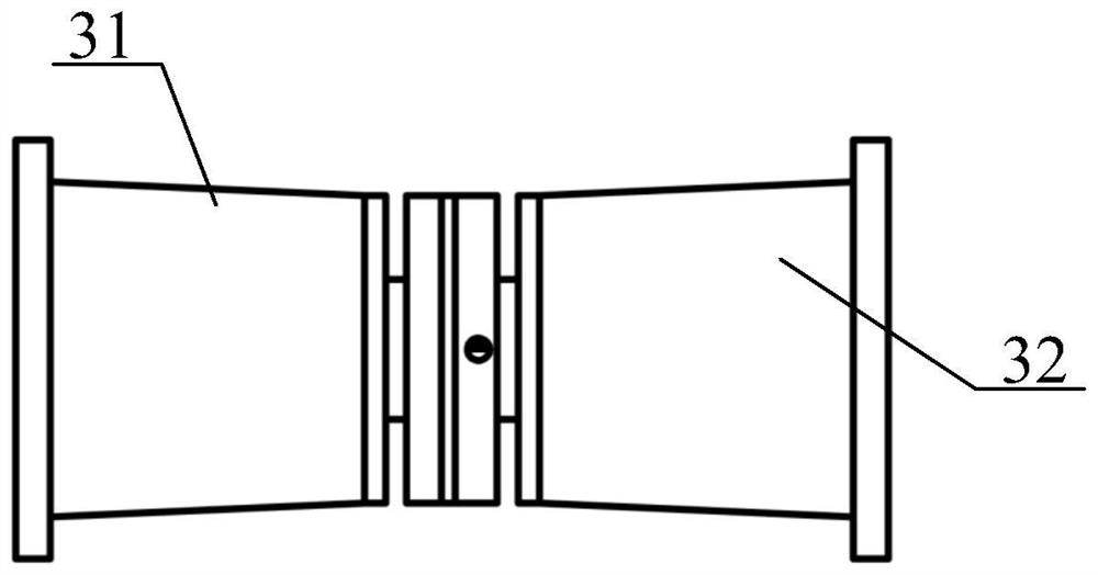
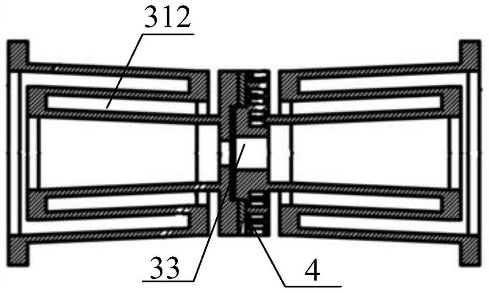
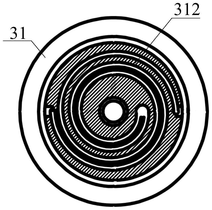
[0031] as attached figure 1 to the attached Figure 4 As shown, the present invention provides a conical labyrinth structure support structure, including an outer tank body 1 of a cryogenic liquefaction vessel, an inner tank body 2 of a cryogenic liquefaction vessel, a conical labyrinth support structure 3 and a thermal insulation pad 4, The tapered labyrinth support base structure 3 is embedded in both ends of the outer tank body 1 of the cryogenic liquefaction container and the inner tank body 2 of the cryogenic liquefaction container; the tapered labyrinth support seat structure 3 also includes: The left conical return labyrinth connection seat 31, the right conical return labyrinth connection seat 32 and the threaded hole 33; the left conical return labyrinth connection seat 31 and the right conical return labyrinth connection seat 32 The threaded holes 33 are opened at the inner middle position of the left conical labyrinth connection seat 31 and the right conical labyri...


PUM


Abstract

The invention provides a conical concentric-square-shaped labyrinth structure supporting structure which comprises an outer tank body of a cryogenic liquefaction container, an inner tank body of the cryogenic liquefaction container, conical concentric-square-shaped labyrinth supporting seat structures and heat insulation pads, and the conical concentric-square-shaped labyrinth supporting seat structures are embedded in the two ends of the outer tank body of the cryogenic liquefaction container and the two ends of the inner tank body of the cryogenic liquefaction container; the conical concentric-square-shaped labyrinth supporting seat structure further comprises a left conical concentric-square-shaped labyrinth connecting seat, a right conical concentric-square-shaped labyrinth connecting seat and threaded holes. The interiors of a left-side conical concentric-square-shaped labyrinth connecting base and a right-side conical concentric-square-shaped labyrinth connecting base are each of a double-vortex-line cavity structure. According to the structure, the heat exchange area is increased while the structural mechanical strength is guaranteed, the gas-solid heat exchange performance is far better than that of a hollow cavity, a low-temperature chamber is additionally arranged in the middle of the support, heat sink is added to the support, the temperature gradient of the support is reduced, the heat insulation performance of the support is improved through low-temperature gas precooling, and cold leakage is further reduced.

Description

technical field [0001] The invention belongs to the technical field of connecting equipment for cryogenic dissolved gas tanks, and in particular relates to a support structure of a conical return labyrinth structure. Background technique [0002] For cryogenic containers such as LNG liquefied gas transport vehicles, the interlayer gap between the outer shell and the inner liner is relatively small, and the inner liner is insulated by wrapping paper. It is necessary to avoid scratching when assembling. In order to ensure the high concentricity of the inner and outer containers, To avoid scratches during assembly, it is necessary to ensure that the inner and outer containers are accurate, stable and easy to assemble when assembling. The steps of the current pairing method are as follows: an iron plate with an arc is placed on the inner side of the outer container, a sliding car is placed on the iron plate, a traction rope is arranged on the sliding car, and a hanging rope is u...

Claims


Application Information

Patent Timeline
IPC IPC(8): F17C3/04F17C3/02
CPCF17C3/04F17C3/02F17C2203/03F17C2201/01Y02E60/32
Inventor 魏颖冯宪高
Owner 中太(苏州)氢能源科技有限公司
Why Eureka
Try Eureka