Eureka AIR delivers breakthrough ideas for toughest innovation challenges, trusted by R&D personnel around the world.

Steel sheet and steel pipe

A steel plate and plate thickness technology, applied in the field of steel plates and steel pipes, can solve the problems of reduced surface hardness, slowed surface cooling rate, and insufficient central structure control, etc., to achieve excellent SSC resistance, HIC resistance, and excellent low temperature toughness Effect

Pending Publication Date: 2022-08-02
NIPPON STEEL CORP
View PDF14 Cites 0 Cited by
  • Summary
  • Abstract
  • Description
  • Claims
  • Application Information

AI Technical Summary

Problems solved by technology

[0011] However, in the techniques described in these documents, the hardness of the surface layer is lowered by reducing the cooling rate of the surface layer on average by cooling including reheating in cooling the steel sheet.
Therefore, these techniques cannot sufficiently control the structure of the central portion, and may not be able to meet the higher demand for low temperature toughness (DWTT).

Method used


Image

  • Steel sheet and steel pipe
  • Steel sheet and steel pipe
  • Steel sheet and steel pipe

Examples


Embodiment ( Embodiment 1

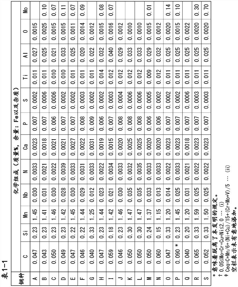
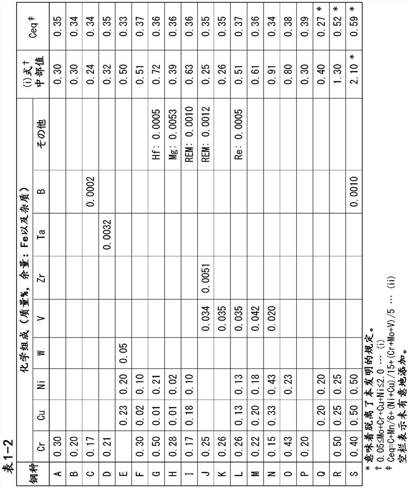
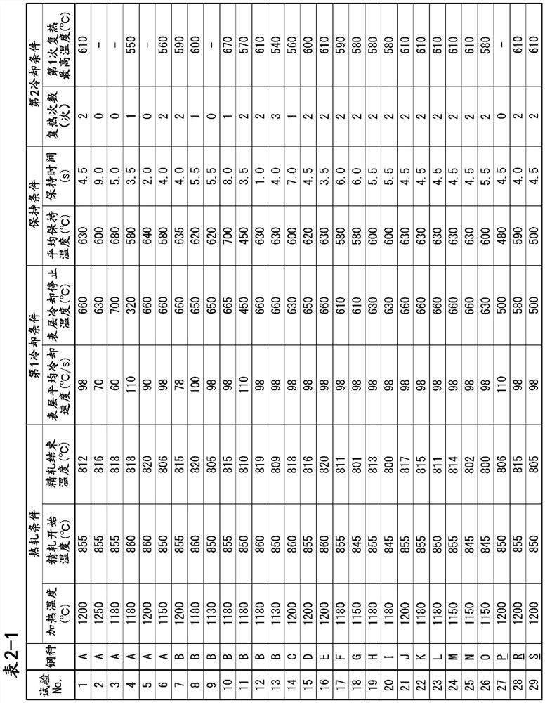
[0234] Steels having the chemical compositions shown in Table 1-1 and Table 1-2 were melted and continuously cast to obtain billets. For the thickness at this time, steel types J to N were set to 300 mm, and other steel types A to I and O to S were set to 240 mm. As shown in Tables 2-1 and 2-3, the obtained slabs were heated to a temperature range of 1100 to 1250°C, hot rolled in a recrystallization temperature range exceeding 900°C, and then subjected to Ar3 to 900°C. In the hot rolling (finishing rolling) in the non-recrystallization temperature region, the hot rolling was completed at the temperature shown in Table 2-1 and Table 2-3, which is the temperature (° C.) of Ar3 or higher.

[0235] After that, for some examples, the first cooling step, the holding step, the third cooling step, and the fourth cooling step were sequentially performed under the conditions shown in Tables 2-1 to 2-4, and thereafter, cooling and cooling were repeated. The steel sheet was produced by c...

Embodiment 2

[0278] Among the steel sheets obtained in Example 1, a steel sheet having preferable properties was formed into a tubular shape by the UO pipe-making method, welded from the inner and outer surfaces of the steel pipe by submerged arc welding, and expanded to obtain a UOE steel pipe. Regarding the welding conditions, the inner surface side was made into three electrodes, the outer surface side was made into four electrodes, and the heat energy was set in the range of 2.0 kJ / mm to 10 kJ / mm according to the plate thickness.

[0279] The obtained steel pipe was subjected to metallographic observation, effective crystal grain size measurement, tensile test, surface hardness measurement, DWTT test, Charpy impact test, SSC test, and HIC test in the same manner as the steel sheet.

[0280] However, as for the observation plane of the metal structure in the steel pipe, so that the L (long side) direction cross section becomes the observation plane, two full-thickness samples are cut out...


PUM

PropertyMeasurementUnit
hardnessaaaaaaaaaa
hardnessaaaaaaaaaa
hardnessaaaaaaaaaa

Abstract

A steel sheet having a prescribed chemical composition, the steel sheet having a metallographic structure in the center of the sheet thickness comprising, in area%, 0-80% of polygonal ferrite; the present invention relates to a steel sheet having an effective crystal grain size of 15.0 [mu] m or less, and one or two elements selected from acicular ferrite and bainite, the remainder being an M-A phase, the steel sheet having an effective crystal grain size of 15.0 [mu] m or less, the metallographic structure in a surface layer, which is a range from the surface to 1.0 mm in the thickness direction, containing 95% or more in total in area% of one or two elements selected from acicular ferrite and bainite, and the remainder being an M-A phase, the steel sheet having an effective crystal grain size of 15.0 [mu] m or less, and the steel sheet having an effective crystal grain size of 15.0 [mu] m or less. The surface layer has a maximum hardness of 250 HV0.1 or less.

Description

technical field [0001] The present invention relates to steel sheets and steel pipes. Background technique [0002] In recent years, the production conditions of oil wells and gas wells (hereinafter, oil wells and gas wells are collectively referred to as "oil wells") of crude oil, natural gas, and the like have become severe. The production environment of an oil well increases with the depth of production and contains CO in its atmosphere 2 , H 2 S, Cl - etc., the extracted crude oil and natural gas also contain more H 2 S. [0003] Therefore, the requirements for the performance of the line pipes transporting them have also become strict, with high resistance to sulfide stress corrosion cracking (hereinafter also referred to as "SSC resistance") and resistance to hydrogen induced cracking (hereinafter also referred to as ""SSC resistance") Steel pipes for line pipes with HIC resistance") and steel sheets for line pipes serving as raw materials of the steel pipes are i...

Claims


Application Information

Patent Timeline
Patent Type & Authority Applications(China)
IPC IPC(8): C22C38/00C22C38/58
CPCC22C38/02C22C38/04C22C38/12C22C38/26C22C38/002C22C38/14C22C38/28C22C38/22C22C38/16C22C38/20C22C38/42C22C38/44C22C38/32C22C38/005C21D9/08C21D9/46C21D2211/005C21D2211/002C21D8/105C21D8/0205C21D8/0226C21D8/0263C21D1/02C21D9/50C21D1/78C21D2221/10C22C38/58C22C38/001
Inventor 藤城泰志原卓也筿原康浩土井直己湊出
Owner NIPPON STEEL CORP
Why Eureka
Eureka Blog
Learn More