
Battery pole and battery cover plate assembly

A battery cover and battery pole technology, which is applied to battery components, electrical components, circuits, etc., can solve problems such as reducing the utilization rate of end face area, battery thermal runaway, affecting battery electrical performance and safety performance, etc., to improve the structure Strength and service life, no disconnection at the joint surface, and low risk of structural failure

Pending Publication Date: 2022-07-29
SHENZHEN KEDALI IND CO LTD
View PDF0 Cites 0 Cited by
  • Summary
  • Abstract
  • Description
  • Claims
  • Application Information

AI Technical Summary

Problems solved by technology

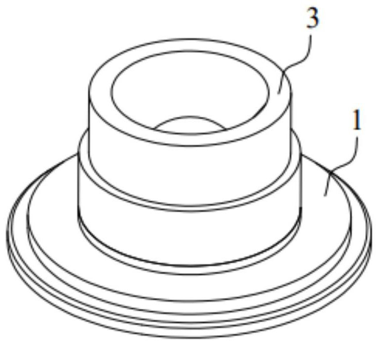
In the process of making battery poles, firstly, the aluminum and copper materials are cut into small pieces of aluminum plates and small pieces of copper plates, and the cut aluminum plates and copper plates are combined by friction welding to form copper-aluminum composite parts , each battery pole needs to be welded separately, and then the copper-aluminum composite is processed into the required shape of the battery pole. When friction welding is used, only one battery pole can be processed in one clamping, and the processing efficiency is low.
In terms of structural reliability, the copper / aluminum joint surface is affected by the rebound force of the sealing ring, and is always under stress, with the risk of fracture and failure
[0004] In the prior art, when the battery pole is in use, the connecting post is outside the battery and connected to the external circuit of the battery, and the substrate is inside the battery and connected to the cell in the battery. When using the battery, the connecting post needs to be connected to the external circuit of the battery. Welding connection, but the end face of the connecting post needs to avoid the riveting area of ​​the terminal / connecting post during welding, which reduces the utilization rate of the end face area, makes the terminal volume too large, and takes up too much battery pack space; at the same time, when copper and aluminum When the bonding surface is inside the cell (the sealing ring is used as the internal / external boundary of the cell), due to electrochemical restrictions, no aluminum should remain on the copper plate, resulting in the maximum area of ​​the copper / aluminum bonding surface being the diameter of the connecting column Size, and the flow capacity of aluminum is much smaller than that of copper, resulting in weak overall flow capacity
With the development of society and the advancement of battery technology, people have higher and higher requirements for the charge-discharge rate of the battery. When the over-current capability is weak, the battery pole will generate a lot of heat and conduct it to the entire battery, thus seriously The electrical performance and safety performance of the battery will be affected, and even the thermal runaway of the battery will occur. Therefore, in order to match the requirements for a higher charge and discharge rate of the battery, it is necessary to increase the cross-sectional area of ​​the battery pole, but the volume and cost of the battery pack also increase. increase

Method used


Image

  • Battery pole and battery cover plate assembly
  • Battery pole and battery cover plate assembly
  • Battery pole and battery cover plate assembly

Examples


Embodiment 1

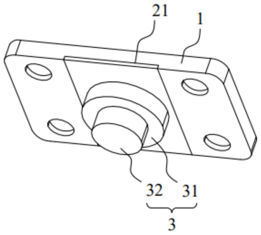
[0037] like figure 2 As shown, this embodiment provides a battery pole, including a substrate 1 and a connecting column 3, the substrate 1 is made of an aluminum plate 2, the substrate 1 is placed outside the battery, and is used to connect with an external circuit of the battery; the connecting column 3 is made of The copper plate 4 is made, one end of the connecting column 3 is fixedly connected with the base plate 1, and the other end is used for connecting with the internal cells of the battery. The battery pole structure in the present invention is completely opposite to the battery pole structure in the prior art. The surface of the substrate 1, which is the terminal surface of the battery pole, is an integral plane. The battery pole and the battery external circuit are welded by welding. When connecting, while keeping the welding area of ​​the substrate 1 unchanged, the overall area of ​​the substrate 1 is smaller, which saves the space of the battery pack; The substr...

Embodiment 2

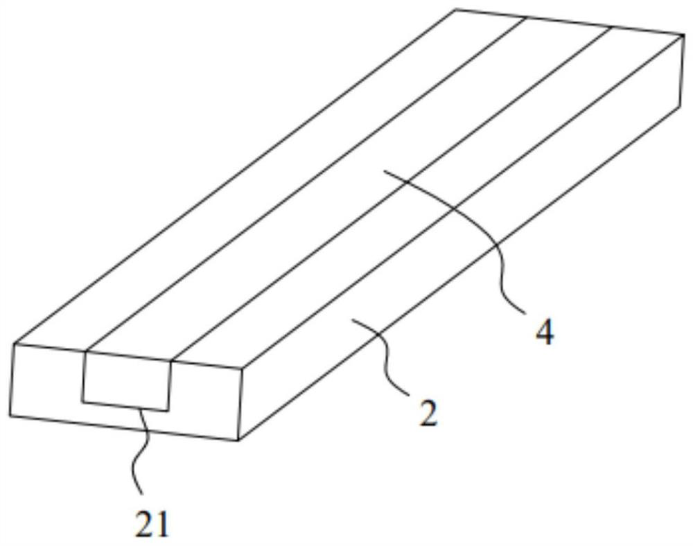
[0050] like Figure 7 As shown, the difference from the first embodiment is that when the battery pole is produced, when the copper-aluminum composite plate is hot-rolled, a through groove 21 is opened on the surface of the aluminum plate 2, and the width of the through groove 21 is equal to the width of the copper plate 4. However, the depth of the through slot 21 is less than the thickness of the copper plate 4, so that after the copper plate 4 is placed in the through slot 21, the surface of the copper plate 4 protrudes from the surface of the aluminum plate 2, and then the copper plate 4 and the aluminum plate 2 are subjected to hot rolling treatment, although some difficulties in hot pressing are increased. However, only a small part of the copper plate 4 is embedded in the aluminum plate 2, which further reduces the consumables of copper and aluminum, and further improves the utilization rate of materials.


PUM


Abstract

The invention belongs to the technical field of batteries, and discloses a battery pole and a battery cover plate assembly.The battery pole comprises a substrate and a connecting column, the substrate is made of an aluminum plate, and the substrate is arranged outside a battery and used for being connected with an external circuit of the battery; the connecting column is made of a copper plate, one end of the connecting column is fixedly connected with the substrate, and the other end of the connecting column is used for being connected with an internal battery cell of the battery. According to the utility model, the structure has better overcurrent capability, lower structure failure risk and higher safety, and the space of the battery pack can be saved at the same time.

Description

technical field [0001] The present invention relates to the technical field of batteries, and in particular, to a battery pole and a battery cover plate assembly. Background technique [0002] The battery pole is an important part in the battery that connects the inside and outside of the battery. One end of the battery pole is connected to the external circuit of the battery, and the other end is connected to the internal cell of the battery, so that the battery can realize the function of charging and discharging. [0003] Currently, if figure 1 As shown, the battery poles are mostly composite poles, that is, they have a copper base plate 1 and an aluminum connection pole 3 . In the process of making the battery pole, first, the aluminum material and the copper material are cut into small pieces of aluminum plates and small pieces of copper plates, and the cut aluminum plates and copper plates are combined by friction welding to become copper-aluminum composite parts , e...

Claims


Application Information

Patent Timeline
Patent Type & Authority Applications(China)
IPC IPC(8): H01M50/553H01M50/562H01M50/176H01M50/184H01M50/188H01M50/15
CPCH01M50/553H01M50/562H01M50/176H01M50/184H01M50/188H01M50/15
Inventor 励建炬唐耀辉
Owner SHENZHEN KEDALI IND CO LTD
Learn More