
High-energy grinding machine and using method thereof

A grinding machine and high-energy technology, applied in the field of powder metallurgy, can solve the problems of unstandardized process parameters, many impurities, and low degree of automation, and achieve the effects of ensuring high-efficiency production, simple connection structure, and reducing powder pollution.

Pending Publication Date: 2022-07-29
陕西智奇开物新材料有限公司
View PDF7 Cites 0 Cited by
  • Summary
  • Abstract
  • Description
  • Claims
  • Application Information

AI Technical Summary

Problems solved by technology

The high-energy grinding machine is the main equipment for mechanical alloying. Its basic process is to achieve the circulation of alloy powder particles through the collision and impact of the grinding medium and the continuous cold welding-breaking-re-cold welding-re-breaking repeated process; in this process, The continuous refinement of the microstructure of alloy powder particles will be accompanied by the generation of a large number of defects. The final nanoscale structure and a large number of defects greatly promote solid-state diffusion and reach the state of mechanical alloying at room temperature; while the common grinding machine Generally large-scale equipment is suitable for mass production, which is not conducive to small-batch and customized production; in addition, most of the existing small grinding machines have low energy, low degree of powder alloying, long alloying time leads to many impurities, and automation The degree is low, and the process parameter indicators are not standardized, which is not conducive to the later research and development and material preparation; in addition, most small grinding equipment increases labor costs

Method used


Image

  • High-energy grinding machine and using method thereof
  • High-energy grinding machine and using method thereof
  • High-energy grinding machine and using method thereof

Examples


Embodiment Construction

[0045] The technical solutions in the embodiments of the present invention will be clearly and completely described below with reference to the accompanying drawings in the embodiments of the present invention. Obviously, the described embodiments are only a part of the embodiments of the present invention, rather than all the embodiments. Based on the embodiments of the present invention, all other embodiments obtained by those of ordinary skill in the art without creative efforts shall fall within the protection scope of the present invention.

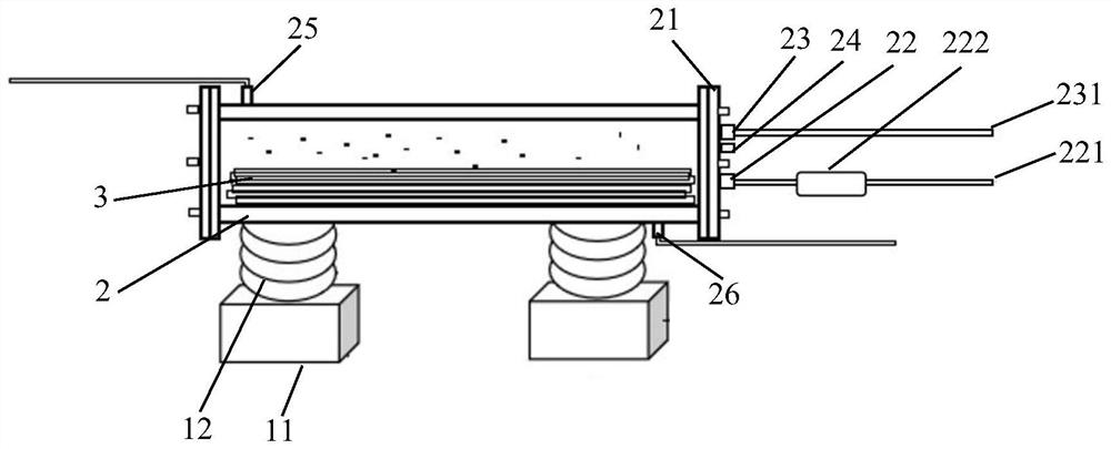
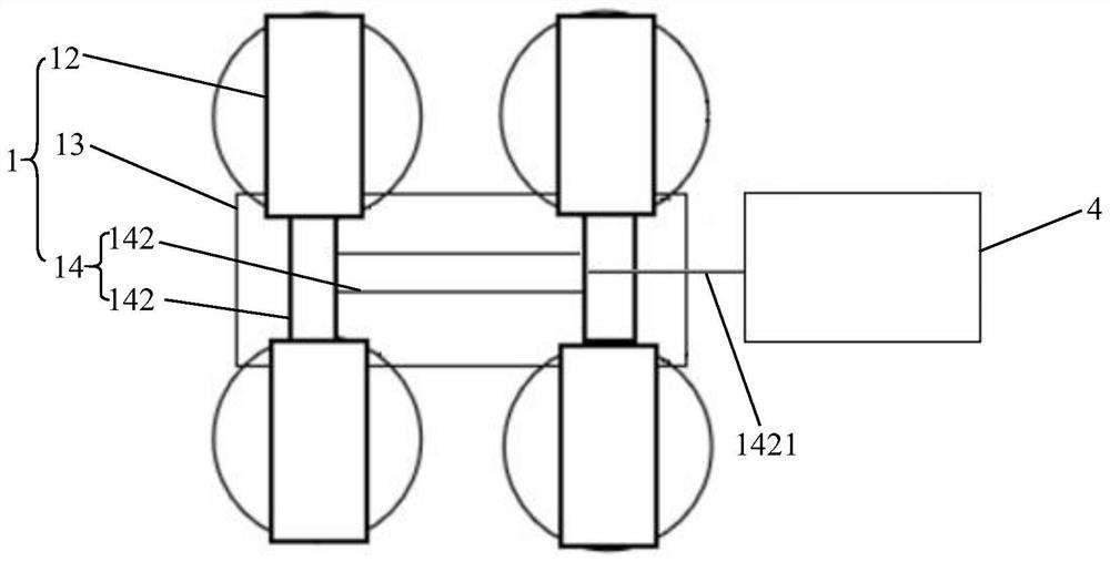
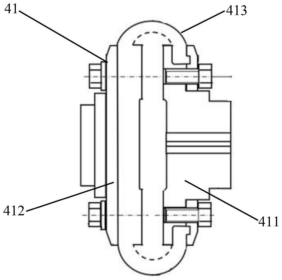
[0046] see attached figure 1 to the attached image 3 , the embodiment of the present invention discloses a high-energy grinding machine, including:

[0047] base;

[0048] Adjustable vibration mechanism 1; Adjustable vibration mechanism 1 is fixed on the base;

[0049] Grinding tank 2; Grinding tank 2 is a cylindrical structure, horizontally and detachably connected to adjustable vibration mechanism 1, and grinding tank 2 is used...


PUM

PropertyMeasurementUnit
diameteraaaaaaaaaa

Abstract

The invention discloses a high-energy grinding machine and a using method thereof. The high-energy grinding machine comprises a base, an adjustable vibration mechanism, a grinding tank, a driving mechanism and a control system. The driving mechanism provides power for the adjustable vibration mechanism, the adjustable vibration mechanism vibrates to drive the grinding tank to grind, the rotating speed of the driving mechanism can be controlled through the control system, the grinding state of the grinding tank is monitored in real time, and the grinding state is transmitted to the mobile terminal; the invention further discloses a corresponding use method, and relates to the technical field of powder metallurgy, in particular to a high-energy grinding machine for industrial production and scientific research and development and a use method of the high-energy grinding machine.

Description

technical field [0001] The invention relates to the technical field of powder metallurgy, can be widely used in mechanical alloying to prepare alloy powder materials, and more specifically relates to a high-energy grinding machine for industrial production and scientific research and development and a method for using the same. Background technique [0002] Mechanical Alloying (MA) refers to the long-term intense impact and collision of metal or alloy powder between powder particles and grinding media in a high-energy ball mill or rod mill, so that the powder particles are repeatedly cold welded and fractured. A powder preparation technology that leads to the diffusion of atoms in powder particles to obtain alloyed powder; the method and equipment are simple, easy to produce, the material preparation is less restricted by the equilibrium phase diagram, the synthesis range is wide, and the prepared alloy powder With fine grain size and high energy, it provides alloy powder wi...

Claims


Application Information

Patent Timeline
Patent Type & Authority Applications(China)
IPC IPC(8): B22F9/04
CPCB22F9/04B22F2009/041B22F2009/042
Inventor 席生岐谷臻
Owner 陕西智奇开物新材料有限公司
Learn More