
Laryngeal mask with porous adsorption function and audio-visual monitoring function

A porous adsorption, laryngeal mask technology, applied in the directions of laryngoscope, stethoscope, respirator, etc., can solve the problems such as the inability to place the laryngeal mask safely and effectively, the influence of breathing airflow, and the monitoring of the secretion of the missing laryngeal mask mask, etc., to reduce micro-errors. Effects of suction events, injury reduction, and throat injury reduction

Pending Publication Date: 2022-07-29
复旦大学附属中山医院青浦分院(上海市青浦区中心医院)
View PDF1 Cites 0 Cited by
  • Summary
  • Abstract
  • Description
  • Claims
  • Application Information

AI Technical Summary

Problems solved by technology

However, the device does not have a built-in camera, and the placement process is blind. It cannot visually guide the safe and effective placement of the laryngeal mask. At the same time, it lacks the monitoring of secretions in the laryngeal mask. At the same time, the laryngeal mask belongs to the supraglottic airway. In the actual application process , throat secretions, and poor alignment can affect respiratory airflow
[0006] Therefore, in summary, there is an urgent need for a combination of real-time monitoring and guidance through the built-in camera at the front end of the laryngeal mask and the miniature auscultation device, and the porous adsorption function of the bottom of the mask to reduce perioperative pulmonary complications and throat injuries. The laryngeal mask with porous adsorption function and audio-visual monitoring function, but there is no report about this laryngeal mask with porous adsorption function and audio-visual monitoring function

Method used


Image

  • Laryngeal mask with porous adsorption function and audio-visual monitoring function
  • Laryngeal mask with porous adsorption function and audio-visual monitoring function
  • Laryngeal mask with porous adsorption function and audio-visual monitoring function

Examples


Embodiment

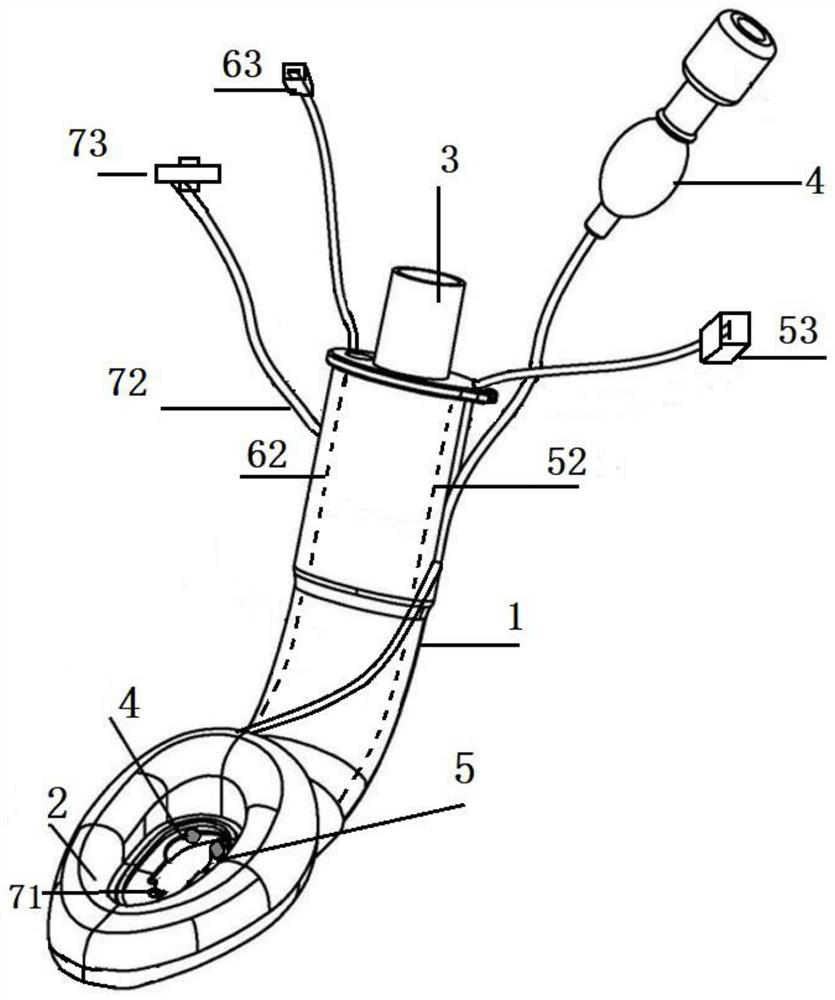
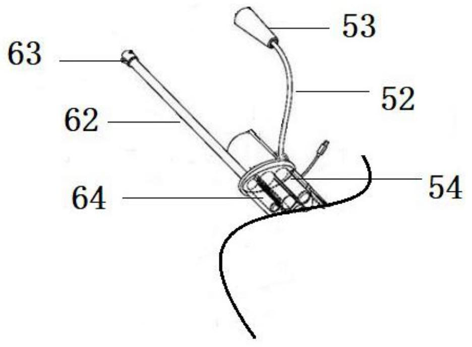
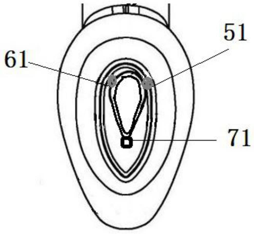
[0032] Please see attached Figure 1-4 shown, attached figure 1 It is a schematic structural diagram of the laryngeal mask with porous adsorption function and audiovisual monitoring function according to the present invention. attached figure 2 It is a partial structural schematic diagram of the laryngeal mask ventilation tube in the laryngeal mask with the porous adsorption function and the audiovisual monitoring function according to the present invention. attached image 3 It is a schematic diagram of the partial structure of the laryngeal mask airbag in the laryngeal mask with porous adsorption function and audiovisual monitoring function described in the present invention. attached Figure 4 It is a schematic diagram of the partial connection of the camera device and the auscultation device in the laryngeal mask with the porous adsorption function and the audiovisual monitoring function according to the present invention.

[0033] The invention combines the built-in...


PUM


Abstract

The invention relates to a laryngeal mask with a porous adsorption function and an audio-visual monitoring function, which comprises a laryngeal mask breather pipe, a laryngeal mask air bag, a trachea cannula and an inflation pipe body, and further comprises a camera device and an auscultation device, and the camera device and the auscultation device are arranged in the laryngeal mask air bag. The camera device comprises a camera, a camera wire, a camera connector and a camera channel. The auscultation device comprises a sound pickup, a sound pickup wire, a sound pickup connector and an auscultation channel. The bottom of the laryngeal mask air bag is further provided with a porous channel, and the porous channel is communicated with the inflation tube body. The laryngeal mask has the advantages that the visual and audible functions are combined, the application of the laryngeal mask in the supraglottic airway is guided and monitored, micro aspiration events are reduced through the porous adsorption function of the bottom of the laryngeal mask body, complications are reduced, the protection function of laryngeal mask anesthesia in the cardiovascular and pulmonary perioperative period is further improved, and throat injuries are reduced.

Description

technical field [0001] The invention relates to the technical field of medical devices, in particular to a laryngeal mask with a porous adsorption function and an audiovisual monitoring function. Background technique [0002] In terms of disease diagnosis and treatment, airway management is a key link in clinical anesthesia and emergency resuscitation. How to quickly and accurately establish a breathing passage has always been the goal pursued by the medical community at home and abroad. Among many airway management tools, the laryngeal mask is the most One of the most widely used ventilation tools in modern clinical anesthesia and pre-hospital emergency-in-hospital emergency-intensive care and treatment. [0003] The laryngeal mask is an airway device consisting of an inflatable leaf-shaped silicone mask and a rubber connecting tube. It can be inserted into the throat through blind insertion or vision through the mouth. The mask can wrap around and seal the epiglottis and ...

Claims


Application Information

Patent Timeline
Patent Type & Authority Applications(China)
IPC IPC(8): A61M16/04A61M16/08A61M16/01A61M16/00A61B1/267A61B1/06A61B7/02A61B7/04
CPCA61M16/04A61M16/08A61M16/0434A61M16/01A61M16/0003A61B1/2676A61B1/0661A61B1/0684A61B7/023A61B7/04A61M2230/40
Inventor 邓利兵
Owner 复旦大学附属中山医院青浦分院(上海市青浦区中心医院)
Learn More