Wind turbine generator loading device
A technology for loading devices and wind turbines, which is applied to wind turbines, monitoring of wind turbines, engines, etc., can solve problems such as damage to reaction force brackets, burning of oil cylinders, and rise in temperature of oil cylinders, so as to improve stability, improve stability and use Lifespan, the effect of avoiding damage
- Summary
- Abstract
- Description
- Claims
- Application Information
AI Technical Summary
Problems solved by technology
Method used
Image
Examples
Embodiment 1
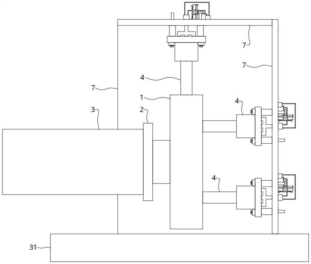
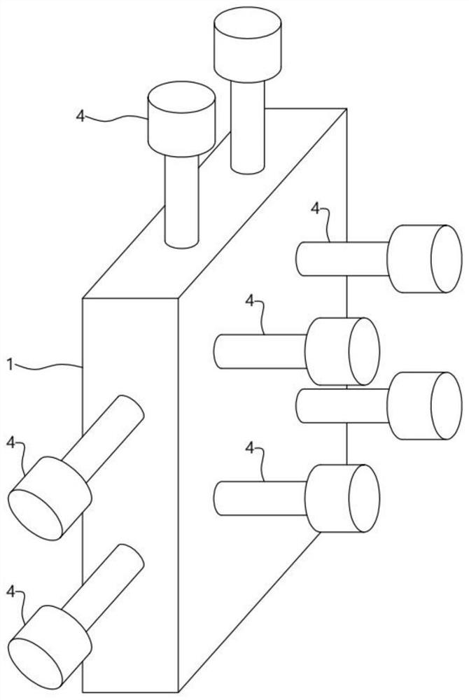
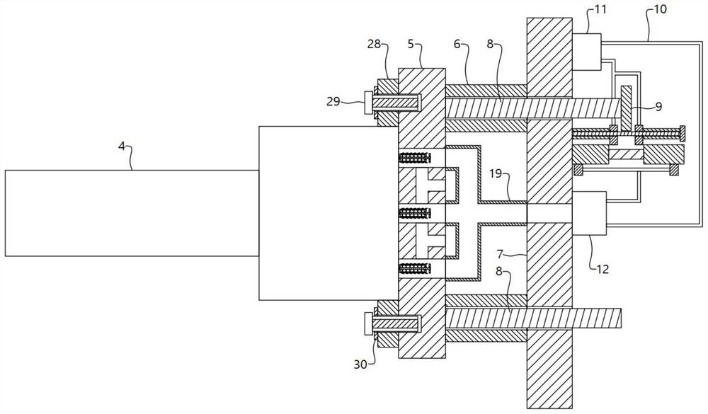
[0032] A wind turbine loading device, comprising a loading plate 1, a connecting flange 2 and a wind power main engine 3 connected in sequence from right to left, the right end of the loading plate 1 is provided with four hydraulic cylinders 4, and the output ends of the four hydraulic cylinders 4 and The right end face of the loading plate 1 is fixedly connected, and the output ends of the four hydraulic cylinders 4 pull the loading plate 1 left and right to simulate the axial force received by the wind power host 3. There are two hydraulic cylinders 4 above the loading plate 1, and the two hydraulic The output end of the oil cylinder 4 is fixedly connected to the upper end face of the loading plate 1 to simulate the longitudinal force and the bending moment caused by the gravity of the wind power main engine 3. Two hydraulic oil cylinders 4 are arranged on the rear side of the loading plate 1, and the two hydraulic oil cylinders 4 The output end is fixedly connected to the re...
Embodiment 2
[0038] The second embodiment optimizes the structure of the heat exchange cylinder 20 on the basis of the first embodiment, that is, the heat exchange cylinder 20 is extended along the direction close to the ventilation hose 19, and the rotating rod 21 is rotated to extend out of the heat exchange cylinder 20 and close to the ventilation hose. One end of 19, and the inner wall and outer wall of the heat exchange cylinder 20 are fixedly connected with a number of heat exchange fins 24, the heat exchange fins 24 are arranged to improve the heat exchange effect of the evaporating liquid and the flowing air, so that the flowing air passes through the heat exchange cylinder 20. At the same time, it can carry more cooling capacity, thereby improving the cooling effect of the hydraulic cylinder 4. An elastic collar 25 is fixedly connected to the inner wall of one end of the heat exchange cylinder 20 near the ventilation hose 19, and the rotating rod 21 slides through the elastic collar...
Embodiment 3
[0040] The third embodiment optimizes the connection structure of the overall device on the basis of the first embodiment, that is, the hydraulic cylinder 4 is integrally connected with a fixed block 28, and the fixed block 28 and the heat dissipation plate 5 are fixedly connected by tightening the bolts 29. , by adopting the connection method of tightening the bolts 29 to facilitate the connection or disassembly of the hydraulic cylinder 4 and the cooling plate 5, and the fixed block 28 is provided with an elastic gasket 30 that squeezes and fits with the end of the tightening bolt 29. The end of the tightening bolt 29 and the pressing surface of the fixing block 28 provide buffers to avoid the problem that the end of the tightening bolt 29 and the pressing surface of the fixing block 28 are damaged due to excessive pressing force. The upper reaction force plate 7 is fixedly connected, and the lower end of the reaction force plate 7 located on the rear side and the right side ...
PUM
 Abstract
Description
Claims
Application Information
 - R&D
- Intellectual Property
- Life Sciences
- Materials
- Tech Scout
- Unparalleled Data Quality
- Higher Quality Content
- 60% Fewer Hallucinations
Browse by: Latest US Patents, China's latest patents, Technical Efficacy Thesaurus, Application Domain, Technology Topic, Popular Technical Reports.
© 2025 PatSnap. All rights reserved.Legal|Privacy policy|Modern Slavery Act Transparency Statement|Sitemap|About US| Contact US: help@patsnap.com


