Lead butt welding machine
A butt welding machine and lead wire technology, applied in the direction of climate sustainability, final product manufacturing, manufacturing tools, etc., can solve problems such as slow equipment speed, increase the number of products, improve the appearance of solder joints, and improve utilization rate and efficiency Effect
- Summary
- Abstract
- Description
- Claims
- Application Information
AI Technical Summary
Problems solved by technology
Method used
Image
Examples
Embodiment 1
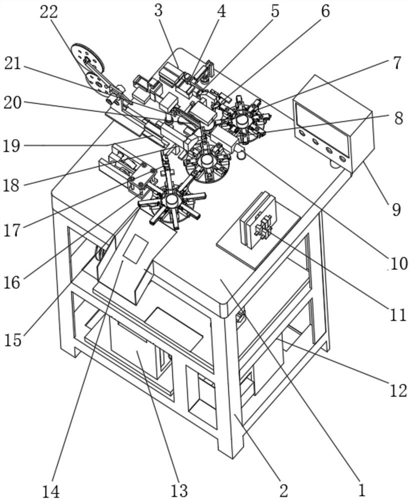
[0023] Example one, by figure 1 Given, the present invention includes a workbench 1, a material lead straightening mechanism 3 is installed on the top of the workbench 1 near the right side, a lead wire feeding mechanism 4 is installed on the front of the material lead wire straightening mechanism 3, and the front surface of the lead wire feeding mechanism 4 is installed A lead wire transfer mechanism 5 is installed, a lead wire cutting mechanism 6 is installed on the front of the lead wire transfer mechanism 5, a molding material feeding structure 22 is installed on the top of the table 1, and a molding aluminum rod transfer mechanism 19 is installed on the front of the molding material feeding structure 22. , the front of the forming material feeding structure 22 is equipped with a forming aluminum rod cutting mechanism 18, and the forming aluminum rod cutting mechanism 18, the inert gas isolation protection mechanism 10 and the forming material feeding structure 22 are all l...
Embodiment 2
[0025] Embodiment 2, on the basis of Embodiment 1, a negative power supply mechanism 21 is installed on the top of the workbench 1, a negative electrode clamping manipulator 20 is installed on the front of the negative power supply mechanism 21, and an inert gas isolation is installed on the front of the negative electrode clamping manipulator 20. The protection mechanism 10, the right side of the inert gas isolation protection mechanism 10 is installed with a positive power supply mechanism 7, the front of the positive power supply mechanism 7 is installed with a positive electrode clamping manipulator 8, a negative power supply mechanism 21, a negative electrode clamping manipulator 20, an inert gas isolation protection mechanism 10. The positive power supply mechanism 7 and the positive clamping manipulator 8 are both located between the molding material feeding structure 22 and the material lead straightening mechanism 3;
[0026] By arranging the negative power supply mech...
Embodiment 3
[0027] Embodiment 3, on the basis of Embodiment 1, a finished product secondary molding detection mechanism 16 is installed on the front of the workbench 1, and a finished product secondary trimming mechanism 17 is installed on the front of the finished product secondary molding detection mechanism 16. The finished product secondary trimming mechanism 17 and the finished product secondary molding detection mechanism 16 are both located on the left side of the formed aluminum bar transfer mechanism 19. The finished product transfer mechanism 15 is installed on the front of the worktable 1. The finished product transfer mechanism 15 and the finished product secondary The trimming mechanism 17 is connected, the finished product transfer mechanism 15 is located on the left side of the forming aluminum bar cutting mechanism 18, and the finished product unloading mechanism 14 is installed on the front of the worktable 1, and the finished product unloading mechanism 14 is located on th...
PUM
 Abstract
Description
Claims
Application Information
 - R&D Engineer
- R&D Manager
- IP Professional
- Industry Leading Data Capabilities
- Powerful AI technology
- Patent DNA Extraction
Browse by: Latest US Patents, China's latest patents, Technical Efficacy Thesaurus, Application Domain, Technology Topic, Popular Technical Reports.
© 2024 PatSnap. All rights reserved.Legal|Privacy policy|Modern Slavery Act Transparency Statement|Sitemap|About US| Contact US: help@patsnap.com


