MPCVD equipment capable of realizing effective doping

A technology of equipment and pipelines, applied in the field of plasma chemical vapor deposition, can solve the problems such as the exploration, research and application realization of in-situ doping technology that restricts MPCVD, less attention to MPCVD research, impurity memory effect and contamination, etc. Doping contamination and memory effect, or the effect of overcoming doping contamination and memory effect and improving utilization

Active Publication Date: 2022-05-31
NANJING UNIV
View PDF14 Cites 0 Cited by
  • Summary
  • Abstract
  • Description
  • Claims
  • Application Information

AI Technical Summary

Problems solved by technology

For the growth of diamond single crystal films, a single reactant—methane is used in MPCVD, and there is no need for complex chemical reaction control. Researchers generally believe that microwave plasma, the source of reactive groups, is the most critical parameter affecting material growth. and most important conditions, therefore, less research attention has been paid to gas transport in MPCVD
[0004] However, the research on material doping is much more complicated. Studies have shown that the main reactive groups for the growth of diamond films are hydrogen atoms generated by high-temperature plasma and the reaction gas methane The molecular reaction leads to the single-carbon and double-carbon groups produced by the decomposition reaction of methane molecules, and the commonly used dopants such as borane and phosphine doped with diamond films usually have a lower decomposition temperature
If the traditional equipment design concept is adopted, it will lead to excessive decomposition of dopants in the high-temperature plasma area and low utilization efficiency. In addition, this excessive decomposition will lead to a large amount of deposition of dopant atoms on the walls of the surrounding relatively low-temperature reaction chamber, causing The very serious impurity memory effect and contamination in the MPCVD reaction chamber seriously restrict the exploration, research and application of MPCVD in-situ doping technology

Method used


Image

  • MPCVD equipment capable of realizing effective doping
  • MPCVD equipment capable of realizing effective doping
  • MPCVD equipment capable of realizing effective doping

Examples


Embodiment 1

[0028] Embodiment 1, the second gas transmission ring 4 is located in the ring gas transmission structure in the center of the support

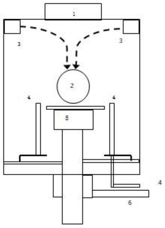
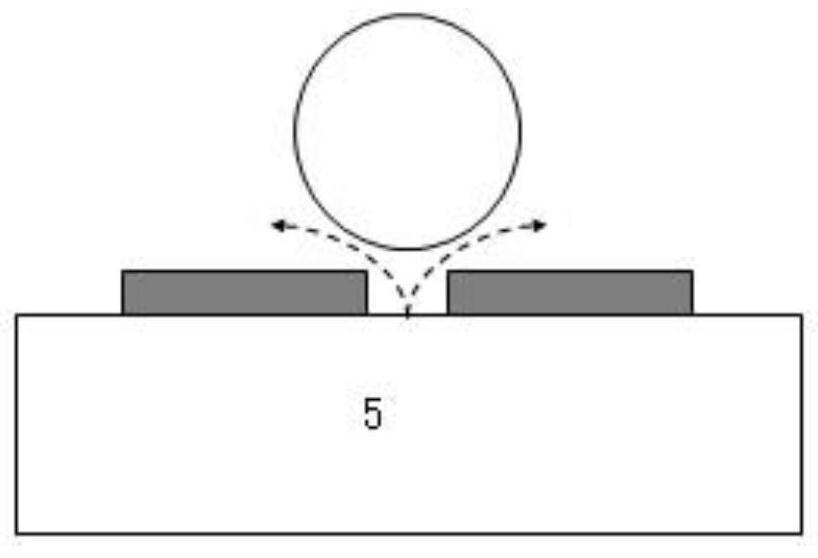
[0029] Open a small hole in the center of the substrate support 5, the diameter of which is less than 0.6 cm, to ensure that its influence on the microwave coupling and the formation of the plasma ball 2 is reduced to a controllable range, and a suitable structure is processed under the substrate support 5, The second dopant gas and buffer gas are introduced from the outside of the reaction chamber to the central gas delivery ring. The center above the reaction chamber is a microwave window 1 .

[0030] The central gas transmission ring adopts a central radial ring structure, and its material can be quartz or corundum, or metal such as stainless steel or molybdenum, such as figure 2 shown.

[0031] The horizontal height difference between the gas injection hole on the second circular ring structure and the support plane is between 0.5 cm a...

Embodiment 2

[0041] Embodiment 2, the structure in which the second gas transmission ring 4 is located around the support and keeps a certain distance from the support

[0042] Fix a circular ring around the substrate support, with a diameter of more than 6cm, and maintain a suitable distance from the edge of the substrate support to ensure that its influence on microwave coupling and plasma ball formation is reduced to a controllable range. And it is coupled with a suitable exhaust structure to ensure the normal and effective discharge of reaction waste gas.

[0043] Process a suitable support and gas connection structure under the substrate support or circular ring, and introduce the second channel of dopant gas and buffer gas from outside the reaction chamber to the surrounding gas delivery ring.

[0044] The surrounding gas transmission ring adopts a circular ring structure radial to the center, and its material can be quartz or corundum, or metal such as stainless steel or molybdenum,...

Embodiment 3

[0055] Embodiment 3, the structure in which the second gas transmission ring 4 is located around the support and in close contact with the support

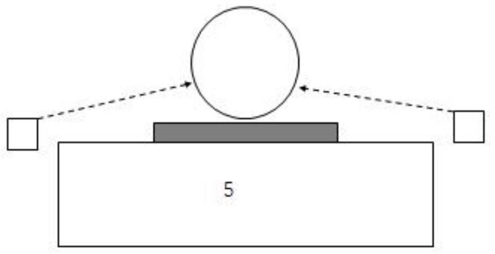
[0056] Fix a circular ring around the substrate support and keep it in close contact with the edge of the substrate support to ensure that its influence on microwave coupling and plasma ball formation is reduced to a controllable range. Appropriate support and gas connection structures are processed below, and the second dopant gas and buffer gas are introduced from the outside of the reaction chamber to the surrounding gas delivery ring, such as Figure 4 shown.

[0057] The central gas transmission ring adopts a central radial ring structure, and its material can be quartz or corundum, or metal such as stainless steel or molybdenum.

[0058] The height difference between the gas injection holes on the circular ring structure and the plane of the support is between 0.5 cm and -0.5 cm, so as to facilitate the control of the spati...


PUM


Abstract

An MPCVD device capable of achieving effective doping comprises a reaction chamber and a gas input structure, the gas input structure comprises two reaction gas pipelines, a distributor connected with the first pipeline evenly conveys gas into the reaction chamber, a gas outlet is located near the top of the reaction chamber, reaction gas is evenly conveyed into the reaction chamber, and the reaction gas is evenly conveyed into the reaction chamber. The gas distributor is located in the top area of the chamber; the first pipeline is used for transmitting a first reactant, the second pipeline is used for uniformly inputting doped reaction gas to the surface of a substrate through a circular ring gas distributor, the horizontal height of a gas transmission ring of the second pipeline is consistent with that of a substrate support, and the gas transmission ring can be placed at the central position and is of an inner concentric structure with the support; the gas transmission ring can also be placed on the periphery of the support, and the gas transmission ring and the support are of an outer concentric structure. According to the invention, the two pipelines are adopted to transmit the reaction gas respectively, so that the doping effect of MPCVD can be effectively realized.

Description

Technical field: [0001] The invention relates to the field of microwave plasma chemical vapor deposition, in particular to the gas input structure of equipment. Background technique: [0002] Microwave plasma chemical vapor deposition (MPCVD) is one of the mainstream techniques for epitaxy of diamond films, and is the best choice for preparing high-quality diamond films. The microwave resonant cavity and plasma ball in the MPCVD reaction chamber are the core of design and attention. After years of research and development, the use of MPCVD technology has been able to grow high-quality diamond single crystal thin film. [0003] In order to broaden the application fields of diamond and give full play to the advantages of diamond's physical and chemical properties, it is necessary to study the doping of diamond thin films. However, there is still a big gap between the research on diamond doping based on MPCVD technology and the single crystal growth technology. In addition to...

Claims


Application Information

Patent Timeline
IPC IPC(8): C23C16/511C23C16/27C23C16/455C23C16/52C30B25/14C30B25/16C30B29/04
CPCC23C16/511C23C16/274C23C16/278C23C16/4558C23C16/279C30B25/16C30B25/14C30B29/04Y02P70/50C23C16/45508C23C16/45561C23C16/4586
Inventor 顾书林刘松民朱顺明叶建东汤琨
Owner NANJING UNIV
Why Eureka
Try Eureka