
Device and method for improving workpiece edge collapse problem through closed-loop control of laser power

A technology of laser power and closed-loop control, which is applied to the improvement of process efficiency, additive manufacturing, and additive processing. It can solve the problems of workpiece sagging, affecting the surface quality and mechanical properties of the workpiece, so as to prolong the service life and improve the collapse of the workpiece. Side issues, inhibiting cumulative effects

Pending Publication Date: 2022-05-27
JIANGSU UNIV
View PDF0 Cites 0 Cited by
  • Summary
  • Abstract
  • Description
  • Claims
  • Application Information

AI Technical Summary

Problems solved by technology

Affected by the cumulative heat effect of the molten pool, the workpiece often appears sagging during the actual cladding process, which seriously affects the surface quality and mechanical properties of the workpiece

Method used


Image

  • Device and method for improving workpiece edge collapse problem through closed-loop control of laser power
  • Device and method for improving workpiece edge collapse problem through closed-loop control of laser power
  • Device and method for improving workpiece edge collapse problem through closed-loop control of laser power

Examples


Embodiment 1

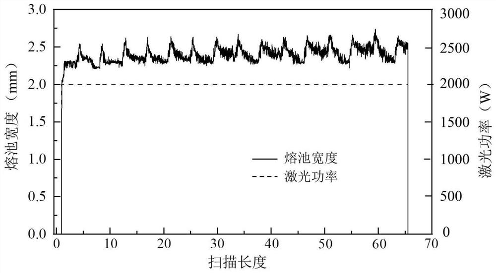
[0050] On the software control integrated platform on the PC side, set the laser control mode to manual, click the record button, and the directional energy deposition equipment starts to work. Monitor and measure real-time melt width curve and power during deposition and manufacturing, and draw curves such as figure 2 shown.

Embodiment 2

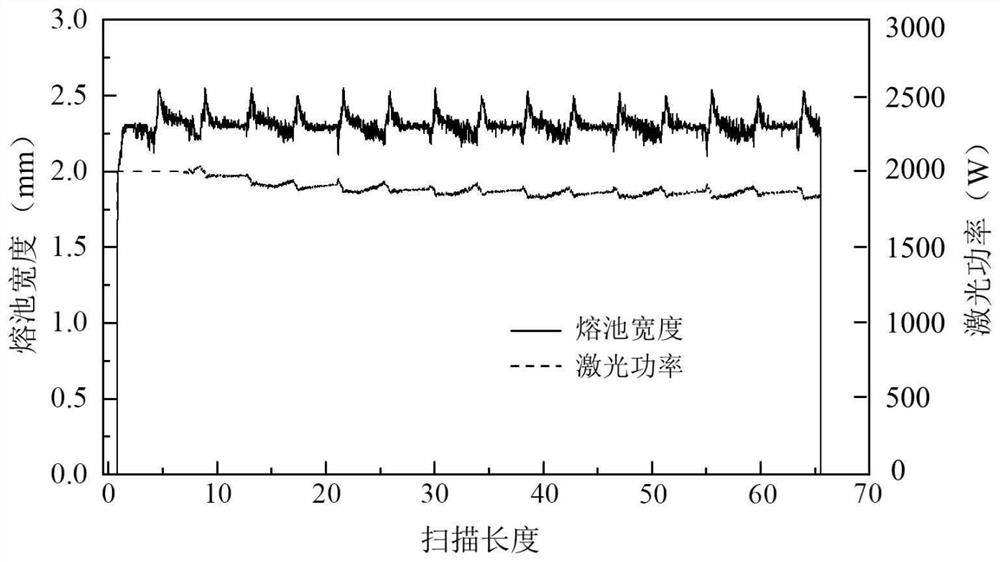
[0052] On the software control integrated platform on the PC side, set the laser control mode to automatic, the reference track parameter to 3, the initial power setting to 2000W, the process power limit to the maximum value of 5000W, the minimum value of 500W, the pixel ratio to 0.333, the threshold value to 1025, and the PID parameter setting. for K P : 200,K I : 500,K D : 100, camera status: connected, laser status: on, the number of single-layer deposition tracks is 12, and the automatic learning number n of the control algorithm is set to 3.

[0053] When depositing the 1st to 3rd tracks, set the first melt pool width detected in the traditional mode as the reference melt width, and use the detected real-time melt width W r (k) and the reference value melting width W i The difference e(k) of (k) is used as the input variable of the PID controller:

[0054] e(k)=W i (k)-W r (k);

[0055] Among them, W i (k) is the reference melting width, W r (k) is the real-time ...


PUM


Abstract

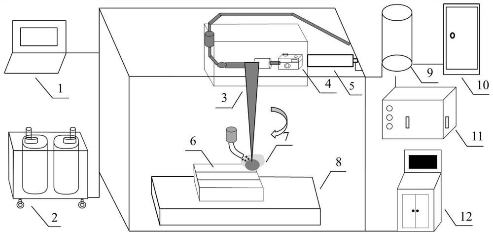
The invention relates to the field of laser cladding quality monitoring, in particular to a device and method for improving the workpiece edge collapse problem through closed-loop control of laser power. In the laser cladding process, a coaxial infrared camera is used for detecting and obtaining a molten pool image in the vertical direction, and the width value of the molten pool is obtained after image processing. The difference value of the detected real-time fusion width and the reference value fusion width serves as an input variable of a PID controller, laser power is regulated and controlled through combination of three control components including proportion, differential and integration, and then the laser power is fed back to a laser directional energy deposition system; according to the method, grain equiaxing is accelerated by improving the thermal gradient, increase of the width of a molten pool and accumulation of the thermal effect are effectively inhibited, the problem of workpiece edge collapse can be remarkably solved, the cladding quality and the material performance are improved, and the service life is prolonged.

Description

technical field [0001] The invention relates to the field of laser cladding quality monitoring, in particular to a device and method for improving the problem of workpiece sagging by closed-loop control of laser power. The real-time monitoring of infrared cameras and the closed-loop control of PID algorithm are used to adjust the laser power, improve the heat accumulation effect of the molten pool and the problem of workpiece slump, and improve the cladding quality and material properties. Background technique [0002] Laser directional energy deposition technology is an emerging processing technology developed in the mid-1980s. It uses layer-by-layer surfacing to manufacture dense metal components. Low cost and high forming efficiency are prominent features, which show obvious advantages in the rapid prototyping technology of large-size and complex parts, and have broad application prospects in aerospace, automobile and ship fields. [0003] The high-energy laser is irradi...

Claims


Application Information

Patent Timeline
IPC IPC(8): B22F10/25B22F10/85B22F12/00B22F12/90B22F10/364B22F10/366B22F10/368B33Y10/00B33Y30/00B33Y50/02
CPCB22F10/25B22F10/85B22F12/00B22F12/90B22F10/364B22F10/366B22F10/368B33Y10/00B33Y30/00B33Y50/02Y02P10/25
Inventor 苏尤宇罗开玉鲁金忠
Owner JIANGSU UNIV
Learn More