Eureka AIR delivers breakthrough ideas for toughest innovation challenges, trusted by R&D personnel around the world.

Process and apparatus for treating tailings

Active Publication Date: 2005-07-14
TRUENORTH ENERGY CORP
View PDF15 Cites 96 Cited by
  • Summary
  • Abstract
  • Description
  • Claims
  • Application Information

AI Technical Summary

Benefits of technology

[0021] The reasons for returning a portion of the discharged solvent recovered tailings component to the solvent recovery apparatus are first, to increase the flowrate of liquids through the solvent recovery apparatus in order to inhibit the accumulation of an asphaltene mat which could plug the solvent recovery apparatus, second, to suppress foam which may be formed in the solvent recovery apparatus and third, to provide an opportunity to liberate and recover additional solvent from the returned portion of the discharged solvent recovered tailings component. As a result, any amount of recycling will be advantageous and the ratio by volume of the returned solvent recovered tailings component to the discharged solvent recovered tailings component may be any ratio which is less than 1:1. Preferably the ratio is greater than about 1:2. Preferably the ratio is no greater than about 5:6.
[0026] Preferably a moderated pressure is provided in the solvent recovery apparatus. Preferably the moderated pressure is between about 1 atmosphere and about 2 atmospheres, which generally represents a pressure reduction prior to the solvent recovery apparatus. The reasons for providing a moderated pressure in the solvent recovery apparatus are first, to minimize slug formation in the transfer lines to the solvent recovery apparatus, second, to minimize transfer line erosion and third, to assist in the breaking of foam which may have been produced during previous processing of the bitumen froth or the tailings component. The moderated pressure may be provided using a pressure relief valve, pressure regulator or any other apparatus or device which is capable of providing the moderated pressure in the solvent recovery apparatus, and may be provided upstream of the solvent recovery apparatus or within the solvent recovery apparatus.
[0072] The purpose of the process of the third aspect and the thickener vessel of the fourth aspect is to recover from the tailings a clarified overflow component, an unclarified overflow component and an underflow component. The objective in separating the overflow component into a clarified overflow component and an unclarified overflow component is to provide the clarified overflow component which can be recycled without further processing and which will not risk fouling of heat exchangers and other apparatus due to the presence of significant amounts of solids and / or other impurities.
[0073] As a result, preferably the process is performed and the thickener vessel is configured to enhance the separation of the tailings into these three components and to maximize the efficiency of the overall tailings treatment process.
[0074] One important mechanism for achieving the purpose of the third aspect and the fourth aspect is effectively configuring the location or locations at which tailings are introduced to the thickener vessel and the locations at which overflow and underflow components are removed from the thickener vessel. A second important mechanism for achieving the purpose is configuring the thickener vessel overall so that the tailings are provided with an opportunity to separate into the three output streams and so that the three output streams are directed towards the appropriate outlets.
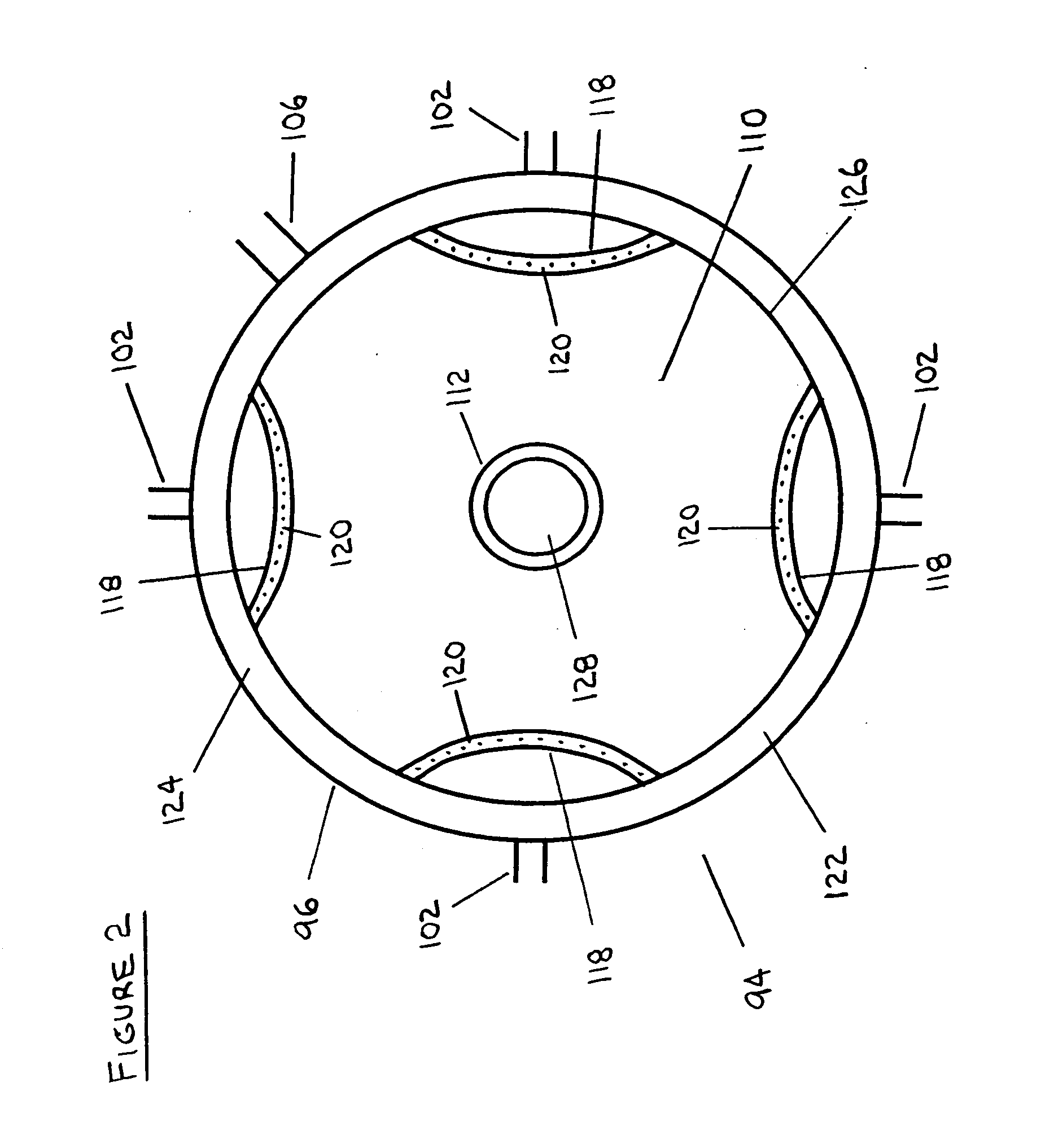
[0089] The thickener vessel may further comprise a baffle arrangement for stilling the clarified overflow component before it is withdrawn from the thickener vessel. The baffle arrangement may also provide a sinuous path for the clarified overflow component to assist in the removal of solids and / or other impurities from the clarified overflow component before it is withdrawn from the thickener vessel.

Problems solved by technology

First, a loss of solvent becomes an unnecessary expenditure of the extraction process.
Second, any solvent remaining in the tailings pond becomes an environmental concern.
Third, water in a tailings pond may be recycled and any solvent remaining in this water may create explosive conditions when reheated for re-use in the various processes.
Since the water recovered from the middlings stream may be heated and recycled for re-use, bitumen remaining in the water may foul heat exchangers and cause a need for increased maintenance of plant equipment.
Complete settlement and consolidation of the fine material suspended in water may take many years.
Furthermore, water not recovered from the middlings stream creates a requirement for makeup water which decreases the overall efficiency of the various processes.

Method used


Image

  • Process and apparatus for treating tailings
  • Process and apparatus for treating tailings
  • Process and apparatus for treating tailings

Examples


Embodiment Construction

[0099] The present invention relates to processes and apparatus for the treatment of product streams from mineral processing operations. The present invention is particularly suited to the treatment of tailings from such processes and is even more particularly suited to the treatment of tailings which comprise relatively fine solids and other impurities.

[0100] In preferred embodiments of the invention, the invention relates to the treatment of tailings obtained from oil sand processing operations and in particular, to the treatment of tailings which are obtained from either the bitumen froth stream or the middlings stream of a process for recovering bitumen from oil sand. In the preferred embodiments, the tailings are obtained from oil sand extraction processes such as the Clark Process or other comparable processes.

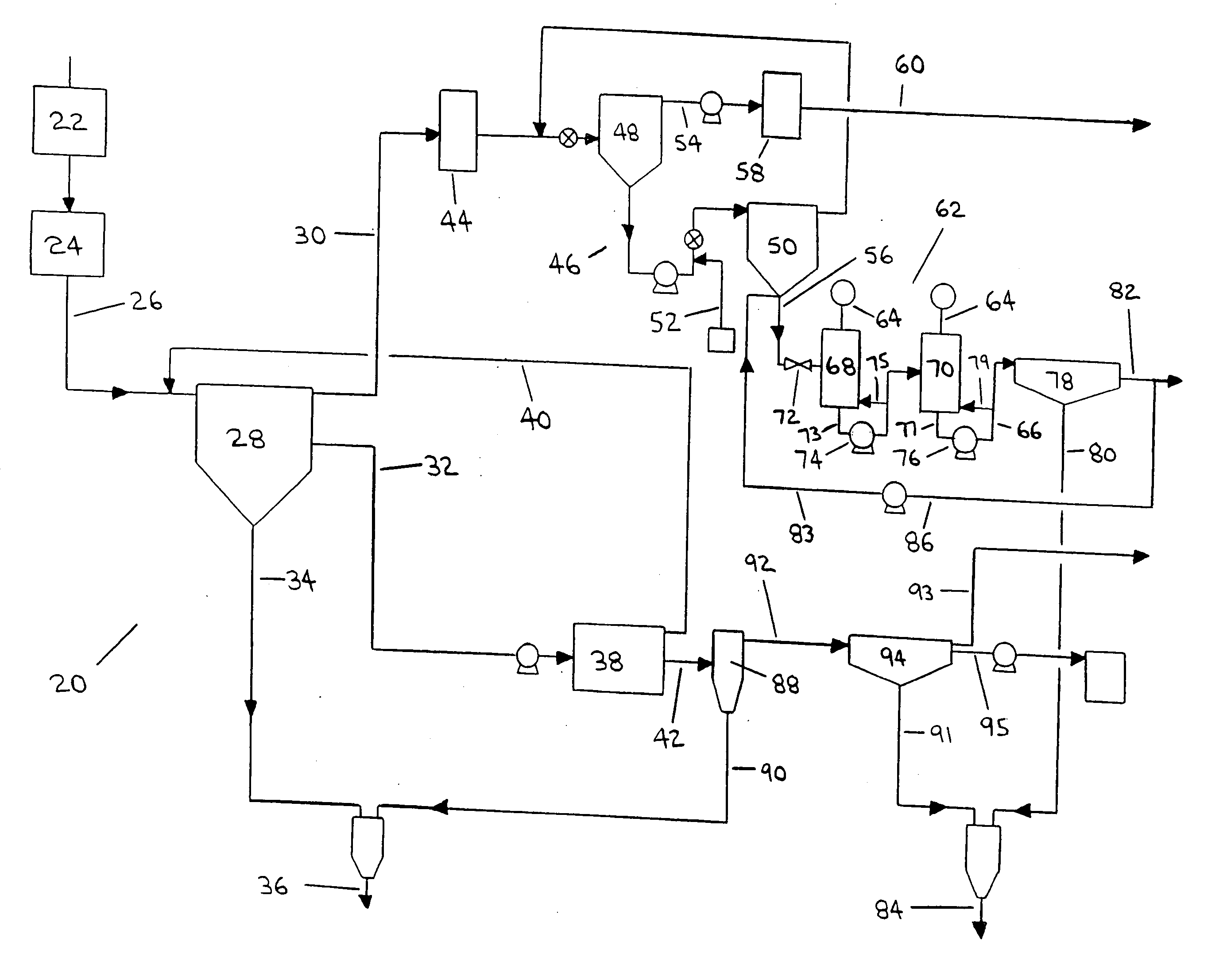
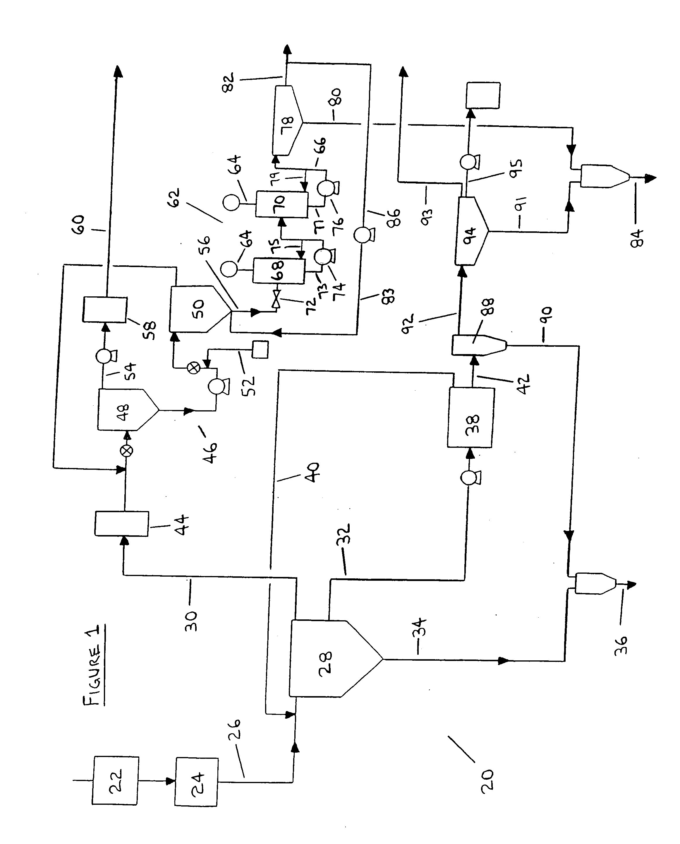
[0101] Preferred embodiments of the present invention are outlined in the flow diagram of FIG. 1, depicting processes of the present invention implemented in conjuncti...


PUM


Abstract

Processes and apparatus for the treatment of product streams from mineral processing operations, including the treatment of tailings which result from oil sand processing operations. The processes and apparatus relate to the recovery of a diluent solvent from bitumen froth tailings and to the thickening of tailings from a bitumen froth stream and a middlings stream resulting from an oil sand extraction process. In one aspect the processes and apparatus relate particularly to the recycling of product streams to maximize process efficiencies. In a second aspect the processes and apparatus relate particularly to the thickening of tailings to produce an underflow component, a clarified overflow component and an unclarified overflow component.

Description

TECHNICAL FIELD [0001] This invention relates to processes and apparatus for the treatment of product streams which result from mineral processing operations, including the treatment of tailings which result from oil sand processing operations. BACKGROUND OF THE INVENTION [0002] Oil sand extraction processes are used to liberate and separate bitumen from oil sand so that the bitumen can be further processed to produce synthetic crude oil. Numerous oil sand extraction processes have been developed and commercialized, many of which involve the use of water as a processing medium. One such water extraction process is the Clark hot water extraction process (the “Clark Process”), which was one of the first commercially successful oil sand extraction processes. [0003] A water extraction process such as the Clark Process typically requires that mined oil sand be conditioned for extraction by being crushed to a desired lump size and then combined with water and perhaps other agents to form ...

Claims


Application Information

Patent Timeline
IPC IPC(8): B03B9/02C02F1/26C02F1/54C02F1/68C10C3/08C10G1/04
CPCC10G1/045C10G1/047C10G2300/206C02F2103/365C10G2300/44C02F1/68C10G2300/4081
Inventor HYNDMAN, ALEXANDER WILLIAMRINGSTROM, JOHN PATRICKSHARPE, JOHNBARTLETT, DOUGLAS ROBERTHINDLE, W. SCOTTGRANT, CHRIS L.
Owner TRUENORTH ENERGY CORP
Why Eureka
Eureka Blog
Learn More