Ultraviolet strip steel pinhole detector grafting system and matched LED light source

An LED light source and detector technology, applied in manufacturing computing systems, optical testing flaws/defects, instruments, etc., can solve problems such as poor safety and stability, facing danger, short service life, etc., achieving a simple and practical structure and strong controllability , the effect of easy promotion

Pending Publication Date: 2022-05-24
杜松
View PDF0 Cites 0 Cited by
  • Summary
  • Abstract
  • Description
  • Claims
  • Application Information

AI Technical Summary

Problems solved by technology

[0004] ①The service life is short, the average life span is 500-800 hours, it may be replaced at any time, the stability is extremely poor, and the cost of the lamp tube is greater than or equal to 10 yuan / hour
[0005] ②High power consumption and low energy efficiency
Only about 20% of the electrical energy is converted into ultraviolet light, and most of the energy is converted into heat and consumed. Not only wasting energy, but also causing difficulty in heat dissipation of the equipment
[0006] ③ Poor safety and stability, 700-800VAC high voltage drive, always facing danger
Halogen lamps have the lowest operating power, and the addition and subtraction of power steps are limited by the transformer coil, so it is impossible to adjust continuously

Method used


Image

  • Ultraviolet strip steel pinhole detector grafting system and matched LED light source
  • Ultraviolet strip steel pinhole detector grafting system and matched LED light source
  • Ultraviolet strip steel pinhole detector grafting system and matched LED light source

Examples


Embodiment Construction

[0031] The technical solutions of the present invention will be clearly and completely described below with reference to the accompanying drawings of the present invention. Based on the embodiments of the present invention, all other embodiments obtained by those of ordinary skill in the art without creative efforts shall fall within the protection scope of the present invention.

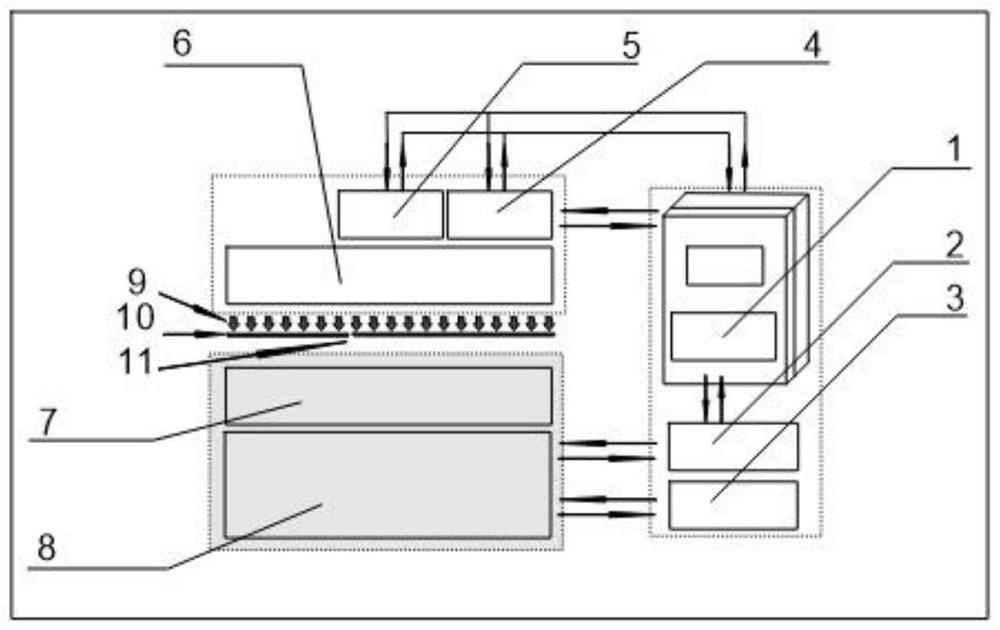
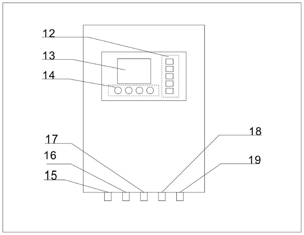
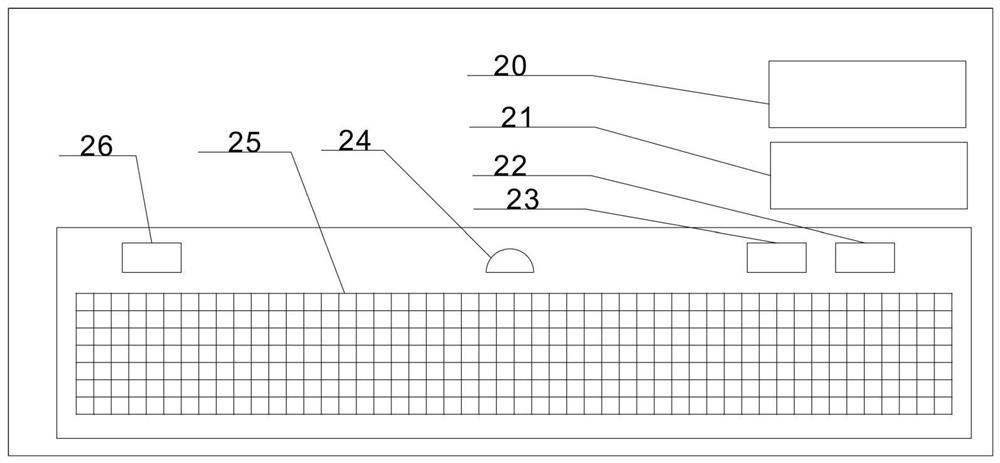
[0032] like Figure 1 to Figure 4 As shown, this embodiment provides a grafting system for an ultraviolet light strip steel pinhole detector and a matching LED light source, including a pinhole detection unit 7 and a pinhole detection controller 8 that are connected to each other in the prior art, and its specific structure and The connection relationship will not be described again. It also includes a main controller 1 , an isolation step-down grafted signal capture unit 2 , an analog high-frequency signal short-circuit module 3 , an LED constant current source 4 , a stroboscopic drive power modul...


PUM


Abstract

The invention discloses an ultraviolet strip steel pinhole detector grafting system and a matched LED light source, comprising a pinhole detection unit and a pinhole detection controller which are connected with each other in the prior art, the system further comprises a main controller, an isolation voltage reduction grafting signal capturing unit, an analog high-frequency signal short circuit module, an LED constant current source, a stroboscopic driving power module and an ultraviolet LED high-frequency light source. The main controller is connected with the pinhole detection controller through the isolation voltage reduction grafting signal capturing unit and the analog high-frequency signal short circuit module, and is connected with the ultraviolet LED high-frequency light source through the LED constant-current source and the stroboscopic driving power module. The device is grafted on an imported original instrument by utilizing mature electronic technologies such as photoelectric coupling isolation and the like, and a halogen light source is replaced by technologies such as an LED (Light Emitting Diode) and the like, so that the defects of high temperature and high pressure, short light source service life, low energy efficiency, high price and the like of the original instrument are overcome. The device has the remarkable advantages of low temperature, low pressure, low load, no ozone, no interference, high controllability and the like, and is simple and practical in structure, low in cost and easy to popularize.

Description

technical field [0001] The invention relates to the fields of electronic information technology and instrumentation, in particular to a grafting system of an ultraviolet light strip steel pinhole detector and a matching LED light source. Background technique [0002] Ultraviolet light strip steel pinhole detector grafting system is a device that detects the quality defects of strip steel pinholes by irradiating ultraviolet light to moving strip steel. It is generally composed of ultraviolet light source, light sensing detection unit, and computing main control unit. It is currently widely used in domestic cold-rolled strip steel manufacturing enterprises. And most mainstream models are monopolized by overseas manufacturers. Light source spare parts are expensive and have a limited lifespan. According to the general market rules, if you want to replace the LED light source system, you must replace the whole machine, which will have a great impact on the factory's production ...

Claims


Application Information

Patent Timeline
Patent Type & Authority Applications(China)
IPC IPC(8): G01N21/88G01N21/894H05B45/30H05B45/345H05B45/34H05B45/3725H05B45/50H05B45/37H05B45/325
CPCG01N21/8806G01N21/894H05B45/30H05B45/345H05B45/34H05B45/3725H05B45/50H05B45/37H05B45/325Y02P90/30
Inventor 杜松杨杰柯俊郑武
Owner 杜松
Why Eureka
Try Eureka