Thermal insulation material disassembling machine capable of adapting to bent shape
A thermal insulation material, bending technology, applied in the direction of conveyors, conveyor objects, roller tables, etc.
- Summary
- Abstract
- Description
- Claims
- Application Information
AI Technical Summary
Problems solved by technology
Method used
Image
Examples
Embodiment 1
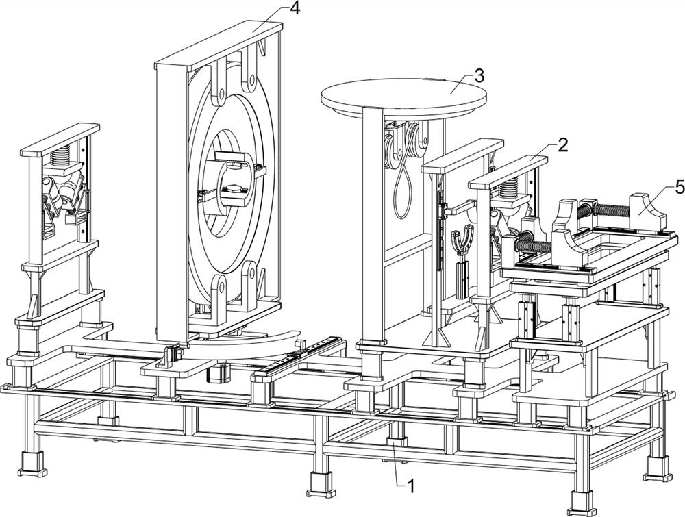
[0041] A dismantling machine for insulation materials that can adapt to curved shapes such as Figure 1-16 As shown, it includes an underframe 1, a transportation system 2, a scraping system 3 and a cleaning system 4; two symmetrical transportation systems 2 are installed on the upper part of the underframe 1; a scraping system 3 is connected to the upper part of the underframe 1; The scraping system 3 is located between the two transport systems 2; the upper part of the chassis 1 is equipped with a cleaning system 4; the cleaning system 4 is located between the two transport systems 2, and the cleaning system 4 is located on the right of the scraping system 3.
[0042] First, the staff moves the insulation material dismantling machine that can adapt to the curved shape to the position where it needs to be used, and then moves the insulation pipe to the left of the transportation system 2 on the left through the external conveying device, and then controls the transportation on...
Embodiment 2
[0044] On the basis of Example 1, such as Figure 1-16 As shown, the transportation system 2 includes a first bracket 201, a first mounting plate 202, a first electric sliding rail 203, a first electric sliding block 204, a first connecting plate 205, a first fixing block 206, and a first elastic member 207. , the first bearing seat 208, the electric roller 209, the second elastic member 2010, the second connecting plate 2011 and the bump 2012; the upper part of the bottom frame 1 is fixedly connected with two symmetrical transportation systems 2; the bottom frame on the left The upper part of 1 is fixedly connected with two front and back symmetrical first brackets 201; the upper part of the two first brackets 201 is fixedly connected with a first mounting plate 202; An electric slide rail 203; a first electric slider 204 is slidably connected to the outer surfaces of the two first electric slide rails 203; a first fixed block 206 is fixedly connected to the opposite sides of...
Embodiment 3
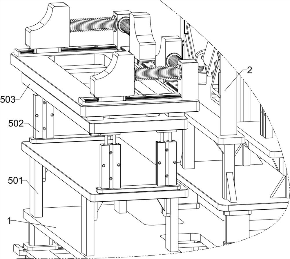
[0054] On the basis of Example 2, such as Figure 1-2 and Figure 17-18As shown, a detection system 5 is also included; the upper part of the chassis 1 is connected with a detection system 5; the detection system 5 is located on the left side of the transportation system 2; the detection system 5 includes a sixth mounting bracket 501, a second electric push rod 502, The third mounting plate 503, the seventh electric sliding rail 504, the seventh electric sliding block 505, the fourth mounting plate 506, the second sliding rail 507, the second sliding block 508, the pressure detection column 509, the fourth elastic member 5010, the A limit block 5011, a third slide rail 5012 and a third slide block 5013; the left part of the bottom frame 1 is fixedly connected with a sixth installation frame 501; the upper part of the sixth installation frame 501 is fixedly connected with four second electric push rods 502; the four second electric push rods 502 are distributed in a rectangle;...
PUM
 Abstract
Description
Claims
Application Information
 - R&D
- Intellectual Property
- Life Sciences
- Materials
- Tech Scout
- Unparalleled Data Quality
- Higher Quality Content
- 60% Fewer Hallucinations
Browse by: Latest US Patents, China's latest patents, Technical Efficacy Thesaurus, Application Domain, Technology Topic, Popular Technical Reports.
© 2025 PatSnap. All rights reserved.Legal|Privacy policy|Modern Slavery Act Transparency Statement|Sitemap|About US| Contact US: help@patsnap.com


