
Fault diagnosis method and system for electronic equipment

A fault diagnosis system and technology for electronic equipment, applied in the field of fault diagnosis, can solve the problems of complex operation mechanism fault propagation, limited application scope, and difficulty in applying large-scale systems, etc., to achieve the effect of improving the accuracy of fault diagnosis.

Pending Publication Date: 2022-04-26
NAVAL AVIATION UNIV
View PDF0 Cites 0 Cited by
  • Summary
  • Abstract
  • Description
  • Claims
  • Application Information

AI Technical Summary

Problems solved by technology

However, due to the development direction of intelligent, complex and nonlinear electronic equipment and the influence of a large number of unmodeled dynamics, it is very difficult to physically model electronic equipment, which limits the application range of model-based diagnostic methods and is difficult to be used. Applied to large-scale systems; at the same time, the operation mechanism of equipment and the propagation of faults in equipment are very complex, which sets a certain threshold for fault diagnosis using expert knowledge

Method used


Image

  • Fault diagnosis method and system for electronic equipment
  • Fault diagnosis method and system for electronic equipment
  • Fault diagnosis method and system for electronic equipment

Examples


Embodiment Construction

[0052] The following will clearly and completely describe the technical solutions in the embodiments of the present invention with reference to the accompanying drawings in the embodiments of the present invention. Obviously, the described embodiments are only some, not all, embodiments of the present invention. Based on the embodiments of the present invention, all other embodiments obtained by persons of ordinary skill in the art without making creative efforts belong to the protection scope of the present invention.

[0053] The purpose of the present invention is to provide a fault diagnosis method for electronic equipment, which improves the accuracy of fault diagnosis of electronic equipment.

[0054] In order to make the above objects, features and advantages of the present invention more comprehensible, the present invention will be further described in detail below in conjunction with the accompanying drawings and specific embodiments.

[0055] figure 1 It is a schem...


PUM


Abstract

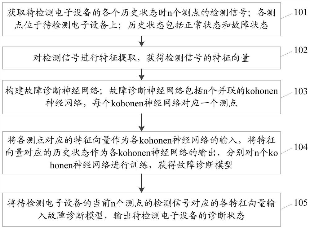
The invention relates to a fault diagnosis method and system for electronic equipment. The method comprises the following steps: acquiring detection signals of n detection points in each historical state of to-be-detected electronic equipment; the historical state comprises a normal state and a fault state; performing feature extraction on the detection signal to obtain a feature vector of the detection signal; constructing a fault diagnosis neural network; the fault diagnosis neural network comprises n kohonen neural networks which are connected in parallel; taking the feature vector corresponding to each measuring point as the input of each kohonen neural network, and respectively training the n kohonen neural networks; and inputting the feature vectors corresponding to the detection signals of the current n detection points of the to-be-detected electronic equipment into the fault diagnosis model to obtain the diagnosis state of the to-be-detected electronic equipment. The fault diagnosis accuracy of the electronic equipment is improved.

Description

technical field [0001] The invention relates to the technical field of fault diagnosis, in particular to a fault diagnosis method and system for electronic equipment. Background technique [0002] In the context of increasingly complex national relations and backgrounds, the training of front-line combat troops is gradually moving closer to actual combat. At the same time, various joint exercises are also developing in the direction of routine and normalization. These actual changes have a great impact on the performance and frequency of use of equipment High requirements have been put forward. In order to meet the needs of the development and use of equipment in the new era, the diagnosis and maintenance methods for electronic equipment have attracted more and more attention from researchers. The traditional maintenance system, which relies on the experience and knowledge of maintenance technicians and regularly checks and repairs equipment through some external equipment, ...

Claims


Application Information

Patent Timeline
IPC IPC(8): G01R31/00G06N3/04G06N3/08
CPCG01R31/00G06N3/04G06N3/08
Inventor 史贤俊吕佳朋肖支才祁亚辉王朕秦亮聂新华
Owner NAVAL AVIATION UNIV
Learn More