
Diamond saw blade for rock plate cutting and manufacturing method thereof

A technology of diamond saw blades and production methods, which is applied in the field of powder metallurgy, can solve the problems of slow cutting speed, poor cutting edge chipping, and high cost of saw blades, and achieve the effects of lowering the melting point, neat edge chipping, and improving comprehensive performance

Pending Publication Date: 2022-04-26
ZHEJIANG PROVINCE YONGKANG CITY JINDU IND & TRADE CO LTD
View PDF0 Cites 1 Cited by
  • Summary
  • Abstract
  • Description
  • Claims
  • Application Information

AI Technical Summary

Problems solved by technology

[0003] The purpose of the present invention is to provide a diamond saw blade for rock slab cutting and its preparation method to solve the problems of high cost, slow cutting speed, short service life, poor edge chipping and trailing of the saw blade in the prior art. The problem

Method used


Image

  • Diamond saw blade for rock plate cutting and manufacturing method thereof
  • Diamond saw blade for rock plate cutting and manufacturing method thereof
  • Diamond saw blade for rock plate cutting and manufacturing method thereof

Examples


Embodiment 1

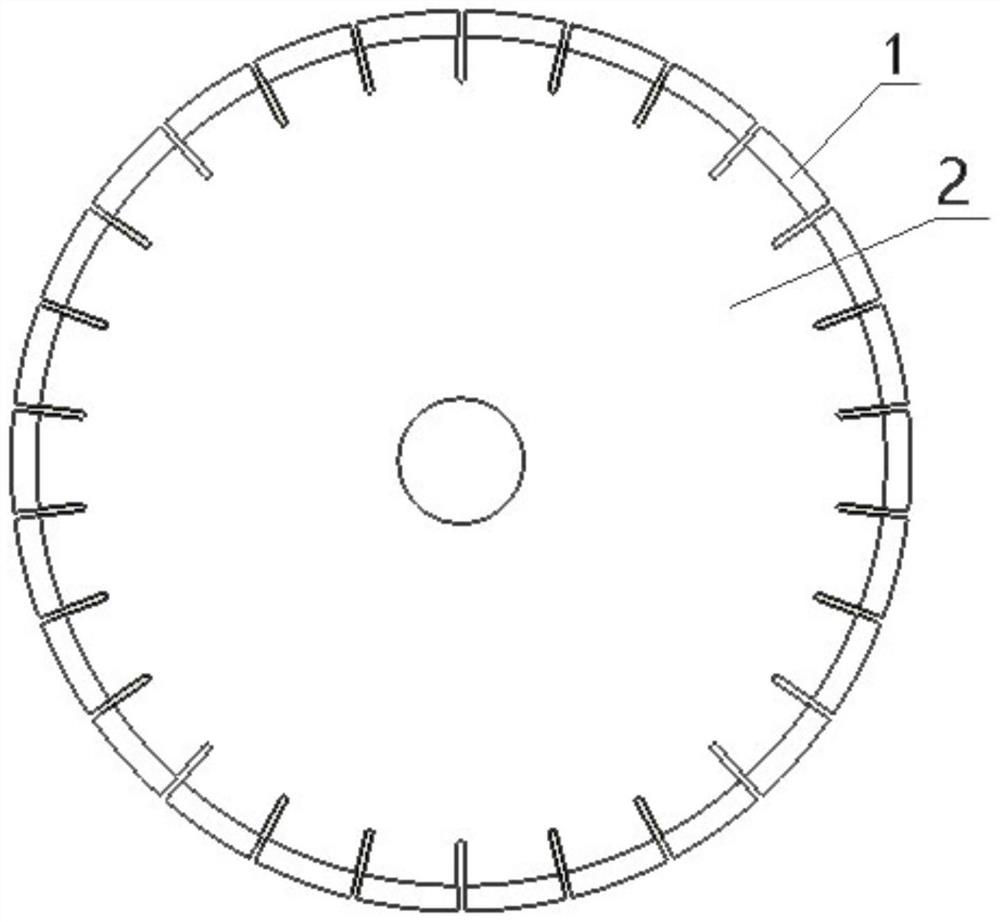
[0030] see figure 1 , a diamond saw blade for cutting rock slabs and a manufacturing method thereof, comprising a cutter head 1 and a base body 2, the cutter head 1 includes raw materials in the following weight percentages: 20-40 parts of copper powder, 10-25 parts of tin powder , 10-30 parts of iron powder, 5-20 parts of superfine cobalt powder, 5-15 parts of nickel powder, 10-15 parts of zinc powder, 1-3 parts of graphite, and the proportion of diamond volume fraction is 10 -30% (by 400%), the diamond particle size is 60-180 orders, specifically comprising the following steps:

[0031] (1) Ingredients: Weigh 40 parts of copper powder, 10 parts of tin powder, 15 parts of iron powder, 5 parts of superfine cobalt powder, 14 parts of nickel powder, 15 parts of zinc powder, and 1 part of graphite, of which the volume fraction of diamond is 10%, the diamond particle size is 60 mesh, and the above raw materials are mixed to obtain alloy matrix powder;

[0032] (2) Mixing: Put th...

Embodiment 2

[0039] The diamond saw blade of this embodiment and its manufacturing method are the same as in Example 1, the difference being that 20 parts of copper powder, 12 parts of tin powder, 15 parts of iron powder, 20 parts of superfine cobalt powder, 15 parts of nickel powder, and 15 parts of zinc powder are weighed. 15 parts and 3 parts of graphite, wherein the volume fraction of diamond is 30%, and the particle size of diamond is 180 mesh. The above raw materials are mixed to obtain alloy matrix powder.

Embodiment 3

[0041] The diamond saw blade of this embodiment and its production method are the same as in Example 1, the difference being that 20 parts of copper powder, 25 parts of tin powder, 30 parts of iron powder, 5 parts of superfine cobalt powder, 5 parts of nickel powder, and zinc powder are weighed. 14 parts, 1 part of graphite, wherein the diamond volume fraction is 15%, and the diamond particle size is 80 meshes. The above raw materials are mixed to obtain alloy matrix powder.


PUM

PropertyMeasurementUnit
Granularityaaaaaaaaaa

Abstract

The invention discloses a diamond saw blade for rock plate cutting and a manufacturing method thereof.The saw blade is composed of a tool bit and a base body, and the tool bit is prepared from, by weight, 20-40 parts of copper powder, 10-25 parts of tin powder, 10-30 parts of iron powder, 5-20 parts of superfine cobalt powder, 5-15 parts of nickel powder, 10-15 parts of zinc powder and 1-3 parts of graphite; wherein the volume fraction of the diamond is 10-30%, the particle size of the diamond is 120-180 microns, and the specific manufacturing method comprises the steps of burdening, mixing, cold press molding, hot press molding and subsequent treatment. Compared with similar products, the diamond saw blade for cutting the rock plate has the advantages that the sharpness is improved by 1-2 times, the service life is prolonged by 2-3 times, the cost is reduced by 20-40%, cut edges are neat, edge breakage and trailing are avoided, and the diamond saw blade has an advanced level in domestic products.

Description

technical field [0001] The invention relates to the field of powder metallurgy, in particular to a diamond saw blade for cutting rock slabs and a preparation method thereof. Background technique [0002] In the prior art, diamond saw blades are generally formulated with a cobalt-based matrix, which has stable performance and good strength and toughness, but the cobalt raw material is expensive, resulting in a higher cost of the saw blade. At the same time, common saw blades for cutting rock slabs on the market still have slow cutting speed, short service life, poor cutting edges, and tailing. Contents of the invention [0003] The purpose of the present invention is to provide a diamond saw blade for rock slab cutting and its preparation method to solve the problems of high cost, slow cutting speed, short service life, poor edge chipping and trailing of the saw blade in the prior art. The problem. [0004] To achieve the above object, the present invention provides the f...

Claims


Application Information

Patent Timeline
IPC IPC(8): B22F5/00C22C26/00C22C9/00C22C9/02C22C9/04C22C9/06C22C30/02C22C30/04C22C30/06B22F1/10B22F3/02B22F3/14B22F3/24B23P15/00B28D1/12
CPCB22F5/00C22C26/00C22C30/02C22C30/04C22C30/06C22C9/00C22C9/02C22C9/06C22C9/04B22F3/02B22F3/14B22F3/24B23P15/00B28D1/121B22F2005/001B22F2003/247
Inventor 胡卫星王哲凌
Owner ZHEJIANG PROVINCE YONGKANG CITY JINDU IND & TRADE CO LTD
Learn More