
High-voltage linear voltage stabilizer

A technology of linear voltage regulator and voltage regulator, which is applied in the direction of instruments, electric variable adjustment, control/regulation system, etc., can solve the problems of limited effect of Miller compensation, difficult control of circuit cost, linear increase of static power consumption, etc., to achieve The whole load range remains stable, which is convenient for miniaturization and packaging, and achieves the effect of performance and cost

Active Publication Date: 2022-04-19
江苏长晶科技股份有限公司
View PDF10 Cites 0 Cited by
  • Summary
  • Abstract
  • Description
  • Claims
  • Application Information

AI Technical Summary

Problems solved by technology

In CN103955251B and CN210983127U patents, the op amp directly uses high-voltage devices without step-down operation, resulting in a very large area of ​​high-voltage devices, and the performance of devices such as transconductance is much lower than that of low-voltage devices
In the patents of CN105955385B, CN103729012B and CN203084588U, since the Zener clamp is used to reduce the voltage and the series resistor is used to limit the current, the overall static power consumption will increase linearly with the increase of VIN. If low power consumption is to be achieved, A very large resistor is required, but it takes up a very large chip area and brings high cost
In the CN203084588U patent, since the combination of high-voltage NJFET and dissipator is not used, the design of low power consumption and exemption from the start-up circuit cannot be realized, and the cost control of the circuit will be more difficult, and because the second stage of the operational amplifier is a follower made of Lv_pmos, There is no gain, so the effect of Miller compensation is very limited, and the compensation in the full load range cannot be realized, which is not conducive to wide load applications

Method used


Image

  • High-voltage linear voltage stabilizer
  • High-voltage linear voltage stabilizer
  • High-voltage linear voltage stabilizer

Examples


Embodiment Construction

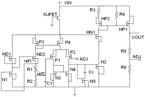
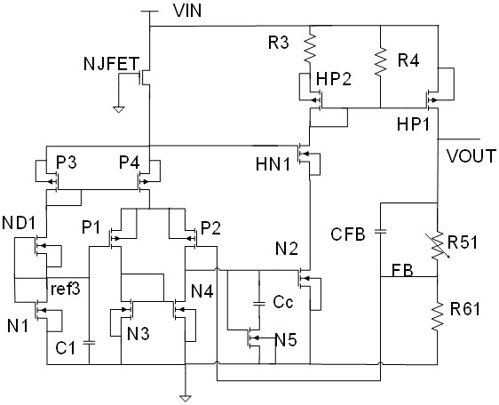
[0011] figure 1 and figure 2 Using the same high voltage drop to low voltage control method, both use high voltage NJFET, low voltage power consumption and high voltage NMOS tube to realize power supply for low voltage circuit, but the internal circuit is slightly different due to the different adjustment methods of the output voltage VOUT. . in figure 1 The feedback resistor for setting the output voltage VOUT is fixed, but the output voltage VOUT can be adjusted by trimming the reference voltage. and figure 2 It is a high-voltage linear regulator with a fixed reference, but the output voltage VOUT can be adjusted by trimming the output feedback resistor. figure 1 high voltage linear regulator for trimming the reference, while the figure 2 The high-voltage linear regulator for trimming the feedback resistor.

[0012] Such as figure 1 , NJFET is a high withstand voltage N-type JFET, ND1 and ND2 are depletion NMOS field effect transistors, N1 / N2 / N3 / N4 / N5 are low-volta...


PUM


Abstract

The invention discloses a high-voltage linear voltage stabilizer, which realizes power supply for a low-voltage circuit by adopting a control mode of reducing high voltage into low voltage and combining an NJFET (Non Junction Field Effect Transistor) tube and a high-voltage NMOS (N-channel Metal Oxide Semiconductor) tube, and comprises two circuits for regulating an output voltage VOUT by trimming a reference voltage and regulating the output voltage VOUT by trimming an output feedback resistor. An extra step-down circuit and a starting circuit are not needed, static power consumption of low-power-consumption application can be obviously improved, meanwhile, dynamic compensation is introduced to achieve effective compensation in a full-load range, under the condition that high-voltage performance is guaranteed, the static power consumption can be obviously reduced, the full-load range is kept stable, miniaturization packaging is conveniently achieved, and cost is reduced. Therefore, the optimal combination of performance and cost is realized.

Description

technical field [0001] The invention relates to a power management circuit, in particular to a high-voltage linear regulator, which belongs to the technical field of integrated circuits and electronic circuits. Background technique [0002] As portable electronic products are widely used in all aspects of work and life, higher requirements are placed on the performance of the power supply, especially the miniaturization and low power consumption of the system. The traditional high-voltage linear regulator can provide excellent anti-power interference ability and is widely used in circuit design. Since the architecture must include a high-voltage to low-voltage step-down circuit, a reference circuit and an operational amplifier circuit at the same time, this structure It usually brings other problems, such as high static power consumption and complex circuit, etc. The high static current will limit the service life of the battery and reduce the working time of portable device...

Claims


Application Information

Patent Timeline
IPC IPC(8): G05F1/56
CPCG05F1/56
Inventor 杨国江王海波
Owner 江苏长晶科技股份有限公司
Learn More