
Sliding type diesel engine valve clamp

A diesel engine and valve clamp technology, which is applied in the direction of manufacturing tools, grinding workpiece supports, furnaces, etc., can solve problems such as the inability to guarantee the valve stability, and achieve the effect of improving the use effect and improving the stability.

Pending Publication Date: 2022-04-15
芜湖匠工精密机械技术有限公司
View PDF3 Cites 0 Cited by
  • Summary
  • Abstract
  • Description
  • Claims
  • Application Information

AI Technical Summary

Problems solved by technology

[0005] In order to solve the above problems, the present invention provides a sliding diesel engine valve clamp, which can solve the problem that the existing clamps proposed in the above background technology cannot guarantee the stability of the valve after clamping

Method used


Image

  • Sliding type diesel engine valve clamp
  • Sliding type diesel engine valve clamp
  • Sliding type diesel engine valve clamp

Examples


Embodiment 1

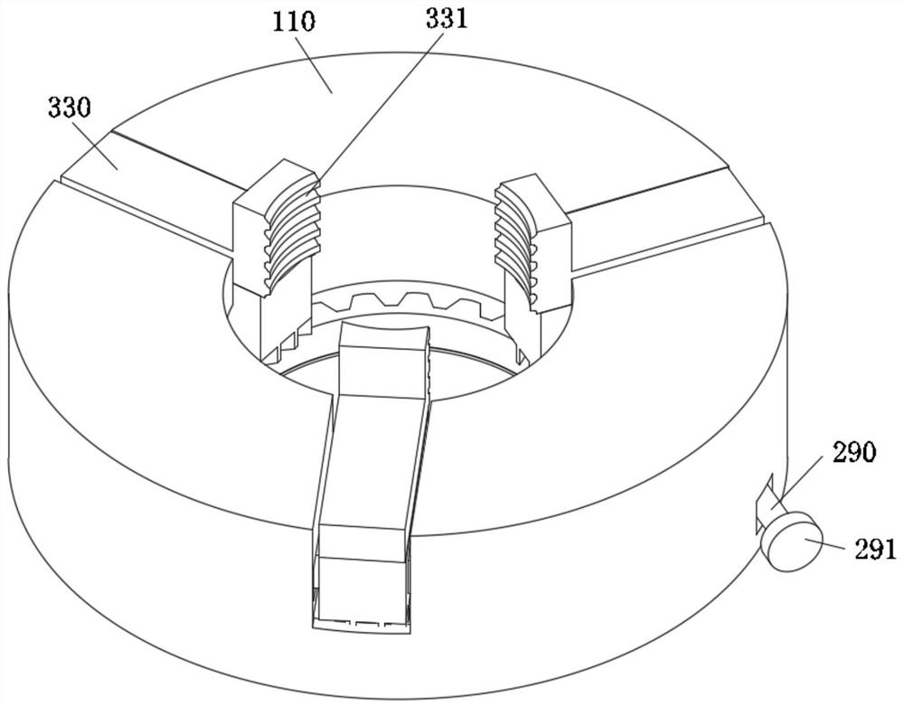
[0033] Such as figure 1 As shown, the shape of the inner side of the clamping block 330 is set as an arc. Through the above-mentioned design, the contact area between the clamping block 330 and the valve stem can be further increased, and the friction assembly includes friction lines 331, and the inner side of the clamping block 330 is opened There are friction lines 331, which can increase the friction force between the clamping block 330 and the valve stem. By increasing the combination of contact area and friction force, the stability of the valve stem after being clamped is greatly improved.

Embodiment 2

[0035] Such as Figure 5 As shown, the main difference of this embodiment is that when the valve head is undergoing heat treatment and shaping, the valve stem needs to move up and down after being centered, the friction assembly includes a fixed side plate 332 and a roller 333, and the inside of the clamping block 330 is fixedly connected with There are two sets of fixed side plates 332, and a roller 333 is connected between the two sets of fixed side plates 332 through a rotating shaft. When the roller 333 contacts the valve stem, the centering of the valve stem is completed, and at the same time, when the valve stem moves up and down, it can drive the roller 333 rotates, thereby reducing the frictional force of the valve stem when moving up and down, ensuring the stability of the valve stem when moving, and reducing the resistance of the valve stem when moving.


PUM


Abstract

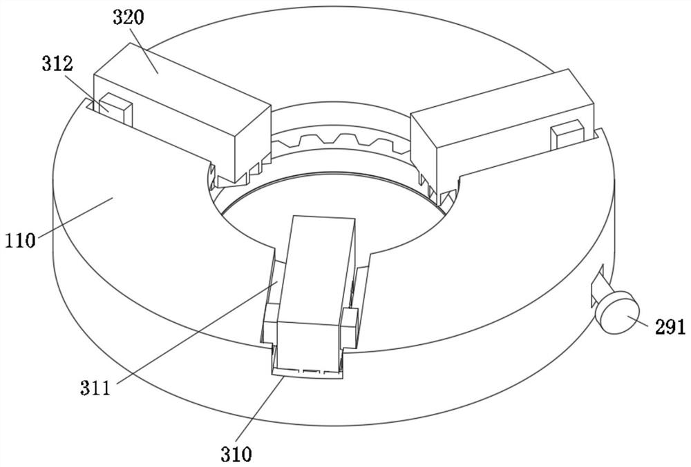
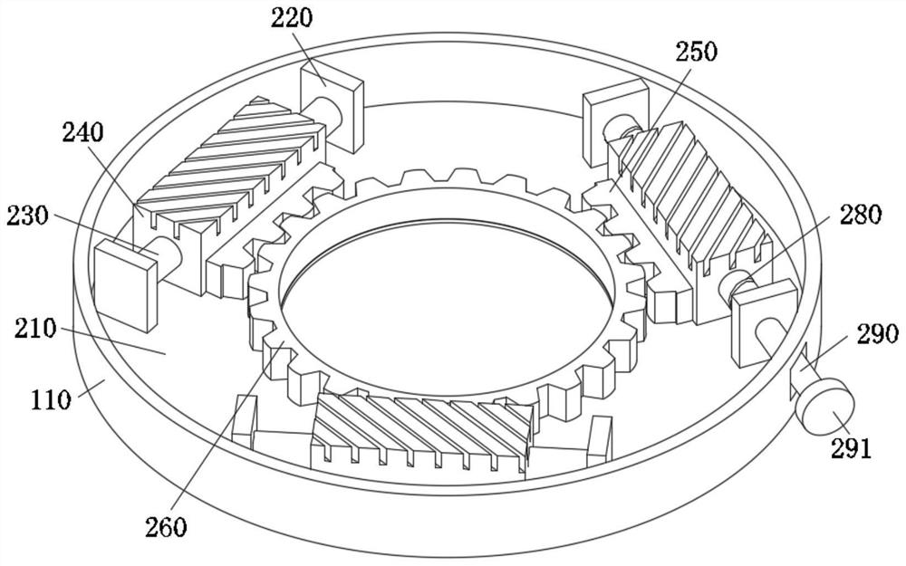
The invention relates to the technical field of diesel engine valves, in particular to a sliding type diesel engine valve clamp which comprises a clamp shell, three sliding ways are formed in the top end of the clamp shell, three sliding bases are arranged in the clamp shell through transmission mechanisms, and the three sliding ways are connected to the sliding bases through sliding mechanisms. Clamping blocks are installed at the top ends of the sliding bases through pins, and friction assemblies are arranged on the inner sides of the three sets of clamping blocks. According to the clamping device, the three sets of clamping blocks are arranged, a valve rod can be clamped and centered, the transmission clamping mode is changed, the valve rod is limited through the three sets of clamping blocks, and the stability of a valve head in the machining process is improved.

Description

technical field [0001] The invention relates to the technical field of diesel engine valves, in particular to a sliding type diesel engine valve clamp. Background technique [0002] The role of the valve is to input air into the engine and discharge the exhaust gas after combustion. The valve is composed of a valve head and a rod. The shapes of the valve head include flat top, spherical top and trumpet top. Generally, it needs to be heat treated and polished. [0003] In order to ensure the stability of the valve during processing, the existing clamps generally clamp the valve, but when the existing clamp clamps the valve, because the valve stem is cylindrical, it is easy to cause the valve to be in the process of processing. There is a certain offset, and the overall stability is poor. [0004] Therefore need a kind of sliding type diesel engine valve clamp to solve above-mentioned problem. Contents of the invention [0005] In order to solve the above problems, the pr...

Claims


Application Information

Patent Timeline
Patent Type & Authority Applications(China)
IPC IPC(8): B24B41/06C21D9/00
CPCB24B41/067C21D9/0068
Inventor 汤东秀沈康钱汤秋芸
Owner 芜湖匠工精密机械技术有限公司
Learn More