Shielding type high-power microwave waveguide phase shift control device
A high-power microwave, phase-shift control technology, applied in electrical components, antenna coupling, antenna arrays, etc., can solve problems such as poor electromagnetic shielding effect and inability to effectively solve electromagnetic compatibility problems.
- Summary
- Abstract
- Description
- Claims
- Application Information
AI Technical Summary
Problems solved by technology
Method used
Image

Examples
Embodiment 1
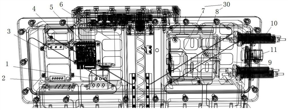
[0025] Such as Figure 1 to Figure 5 As shown, a shielded high-power microwave waveguide phase-shifting control device includes a control system 30 and an optical fiber feedthrough 10 , and the control system 30 communicates with an external host computer through the optical fiber feedthrough 10 .
[0026] Due to the use of optical fiber feedthrough 10, electromagnetic interference signals are prevented from propagating to the control system 30 along the wires, thus solving the problems of the prior art that cannot effectively solve the electromagnetic compatibility problem in the high-power microwave environment, and the electromagnetic shielding effect is not good.
[0027] As a preferred technical solution, the control system 30 includes a power supply module 7 and a photoelectric conversion module 8 electrically connected to each other, and the photoelectric conversion module 8 communicates with an external host computer through the optical fiber feedthrough 10 .
[0028] ...
Embodiment 2
[0038] Such as Figure 1 to Figure 5 As shown, as a further optimization of Embodiment 1, this embodiment includes all the technical features of Embodiment 1. In addition, this embodiment also includes the following technical features:
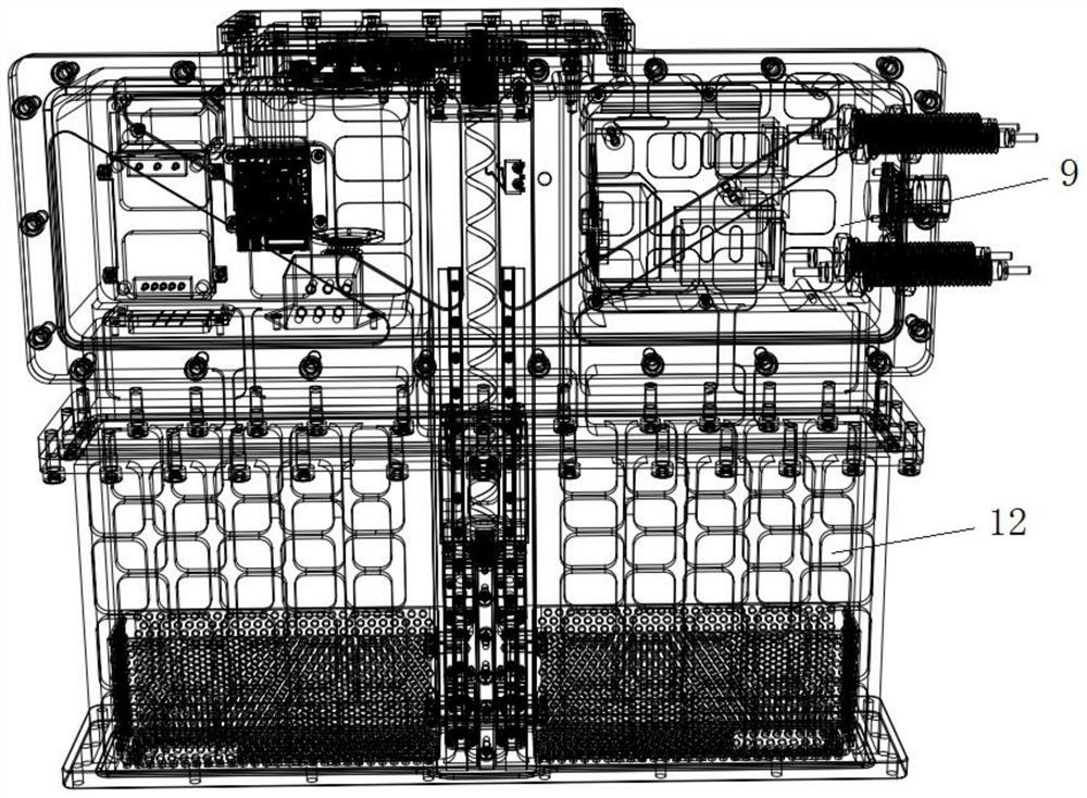
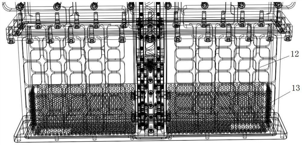
[0039] As a preferred technical solution, a waveguide cavity 12 connected to the shielding cavity 9 is also included.
[0040] The waveguide cavity 12 realizes high-power microwave transmission.
[0041] As a preferred technical solution, the waveguide cavity 12 is provided with a waveguide short-circuit piston 13 .
[0042] The waveguide short-circuit piston 13 realizes the phase change in the waveguide, and at the same time has a certain high-power microwave isolation effect on the shielding cavity 9 .
[0043] As a preferred technical solution, a laser displacement sensor 4 disposed in the shielding cavity 9 is also included, and the laser displacement sensor 4 is used to measure the position of the waveguide short-circuit piston 13 .
...
Embodiment 3
[0048] Such as Figure 1 to Figure 5 As shown, this embodiment includes all the technical features of Embodiment 1 and Embodiment 2. On the basis of Embodiment 1 and Embodiment 2, this embodiment provides a more detailed implementation mode.
[0049] The control system 30 receives the phase-shifting information (moving distance of the waveguide short-circuit piston 1313) sent by the host computer through the optical fiber, sends the phase-shifting signal to the motor controller through the optical fiber feedthrough 10 and the photoelectric conversion module 8, and controls the servo motor 6 to drive the waveguide The piston 13 is short-circuited to realize the phase change of the microwave in the waveguide. After the waveguide phase control is completed, the actual movement distance of the waveguide short-circuit piston 13 is measured by the laser position sensor, and the actual movement distance information of the waveguide short-circuit piston 13 is fed back to the host comp...
PUM
 Abstract
Description
Claims
Application Information
 - R&D
- Intellectual Property
- Life Sciences
- Materials
- Tech Scout
- Unparalleled Data Quality
- Higher Quality Content
- 60% Fewer Hallucinations
Browse by: Latest US Patents, China's latest patents, Technical Efficacy Thesaurus, Application Domain, Technology Topic, Popular Technical Reports.
© 2025 PatSnap. All rights reserved.Legal|Privacy policy|Modern Slavery Act Transparency Statement|Sitemap|About US| Contact US: help@patsnap.com