Cross beam structure strain change rate damage identification method and system

A technology of strain change rate and damage identification, applied in neural learning methods, neural architecture, design optimization/simulation, etc., can solve problems such as inability to quickly identify damage, achieve high engineering application value, strong anti-electromagnetic interference ability, and improve accuracy sexual effect

Pending Publication Date: 2022-03-08
SHANDONG UNIV
View PDF0 Cites 0 Cited by
  • Summary
  • Abstract
  • Description
  • Claims
  • Application Information

AI Technical Summary

Problems solved by technology

[0006] In order to solve the technical problems existing in the above-mentioned background technology, the present invention provides a strain rate change rate damage identification method and system for a beam structure, which is suitable for rapid identification of unknown damage of a beam structure. The element algorithm is used for damage identification to overcome the shortcomings of the traditional damage finite element model that cannot be real-time online and the lack of rapid damage identification caused by the large number of unit nodes. It has the advantages of high sensitivity, fast real-time online identification, and good accuracy.

Method used


Image

  • Cross beam structure strain change rate damage identification method and system
  • Cross beam structure strain change rate damage identification method and system
  • Cross beam structure strain change rate damage identification method and system

Examples


Embodiment 1

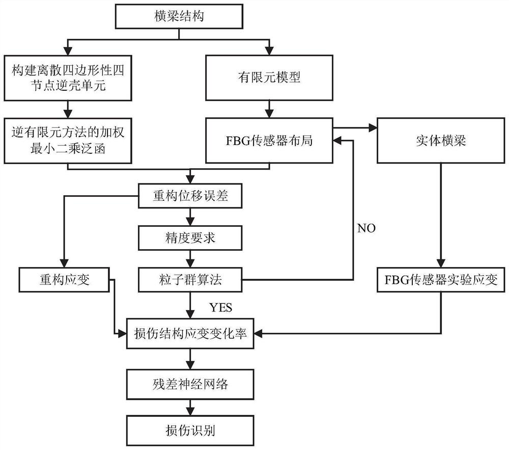
[0043] refer to figure 1 , the present embodiment provides a strain change rate damage identification method for a beam structure, which specifically includes the following steps:

[0044] S101: Discretize the beam structure, and perform virtual layout of the FBG sensor network based on the finite element model.

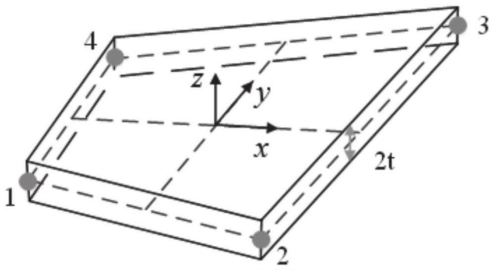
[0045] The beam structure is discretized based on the quadrilateral four-node inverse shell element shown in Fig. 2(a).

[0046] Among them, the quadrilateral four-node inverse shell element (IQS4) is constructed based on the Mindlin plate deformation theory.

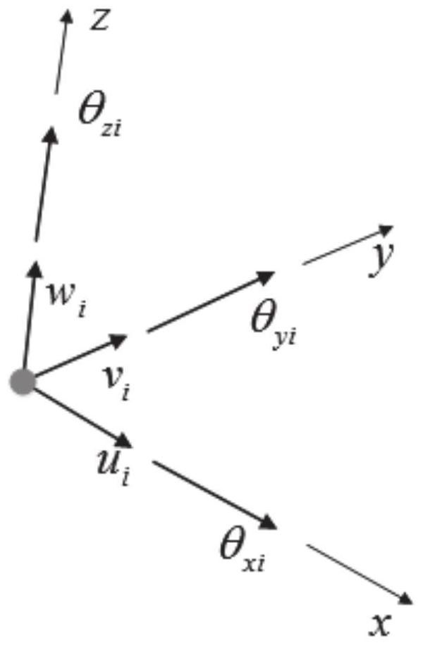
[0047]Specifically, each node of the quadrilateral four-node inverse shell element has 6 displacement degrees of freedom, including three translational degrees of freedom and three rotational degrees of freedom along the X-axis, Y-axis and Z-axis of the Cartesian coordinate system, as Figure 2(b) shows. The thickness of the quadrilateral four-node inverse shell element is 2t, and the displacement mode of th...

Embodiment 2

[0104] This embodiment provides a strain change rate damage identification system for a beam structure, which specifically includes the following modules:

[0105] A virtual layout module, which is used to discretize the beam structure, and perform virtual layout of the FBG sensor network based on the finite element model;

[0106] Displacement reconstruction module, which is used to calculate structural analysis strain based on FBG sensor network virtual layout and weighted least squares function of inverse finite element method, and then perform displacement reconstruction combined with boundary conditions;

[0107] Layout optimization module, which is used to judge whether the FBG sensor layout needs to be optimized according to the reconstruction error, if so, optimize the FBG sensor layout and paste it to the actual beam structure; otherwise, directly lay out the FBG sensor network virtual layout to the actual beam structure structurally;

[0108] Strain change rate calc...

Embodiment 3

[0112] This embodiment provides a computer-readable storage medium, on which a computer program is stored, and when the program is executed by a processor, the steps in the method for identifying the strain change rate damage of the beam structure as described above are implemented.


PUM


Abstract

The invention belongs to the technical field of cross beam structure damage identification, and provides a strain change rate damage identification method and system of a cross beam structure. The method comprises the following steps: discretizing a cross beam structure, and carrying out virtual point distribution on an FBG sensor network based on a finite element model; structural analysis strain is calculated based on FBG sensor network virtual point distribution and a weighted least square generic function of an inverse finite element method, and displacement reconstruction is carried out in combination with boundary conditions; according to the reconstruction error, judging whether the FBG sensor layout needs to be optimized, if so, optimizing the FBG sensor layout and pasting the FBG sensor layout to an actual cross beam structure; otherwise, directly arranging the FBG sensor network on an actual cross beam structure according to a virtual point distribution mode of the FBG sensor network; on the basis of an FBG sensor on an actual cross beam structure, in combination with an inverse finite element method and boundary conditions, full-field reconstruction displacement is obtained, full-field strain is obtained through derivation, and then the strain change rate is obtained; and based on the strain change rate and the residual neural network, positioning and quantifying the damage of the cross beam structure.

Description

technical field [0001] The invention belongs to the technical field of beam structure damage identification, and in particular relates to a strain change rate damage identification method and system of a beam structure. Background technique [0002] The statements in this section merely provide background information related to the present invention and do not necessarily constitute prior art. [0003] As the main load-bearing structure of high-speed trains, the beam structure is mainly subjected to mechanical effects such as side wind loads, vertical loads, and vibration shocks during the operation of the train, causing fatigue cracks in the beams, which seriously affect the safety and reliability of the train. Therefore, it is of great significance to locate and quantify the damage of the cracks generated in the beam structure. [0004] Model-based damage index identification method is a commonly used loss identification technology at present. This method mainly includes ...

Claims


Application Information

Patent Timeline
Patent Type & Authority Applications(China)
IPC IPC(8): G06F30/13G06F30/23G06F30/27G06N3/00G06N3/04G06N3/08G06F119/04
CPCG06F30/13G06F30/23G06F30/27G06N3/08G06N3/006G06F2119/04G06N3/045
Inventor 姜明顺程洋洋张雷隋青美贾磊
Owner SHANDONG UNIV
Why Eureka
Try Eureka