
Steel pipe cutting device and method

A technology of cutting device and cutting method, which is applied to tubular objects, gas flame welding equipment, applications, etc., can solve the problems of narrow site and complex working conditions, and achieve the effect of small site requirements, convenient movement and straight section.

Pending Publication Date: 2022-02-08
中建八局轨道交通建设有限公司
View PDF0 Cites 1 Cited by
  • Summary
  • Abstract
  • Description
  • Claims
  • Application Information

AI Technical Summary

Problems solved by technology

[0006] Aiming at the deficiencies in the above-mentioned prior art, the present invention provides a steel pipe cutting device and method, which solves the technical problem of cutting steel pipes in the prior art where the working conditions are complicated and the site is narrow

Method used


Image

  • Steel pipe cutting device and method
  • Steel pipe cutting device and method
  • Steel pipe cutting device and method

Examples


Embodiment Construction

[0027] The following will clearly and completely describe the technical solutions in the embodiments of the present invention with reference to the accompanying drawings in the embodiments of the present invention. Obviously, the described embodiments are only some, not all, embodiments of the present invention. Based on the embodiments of the present invention, all other embodiments obtained by persons of ordinary skill in the art without making creative efforts belong to the protection scope of the present invention.

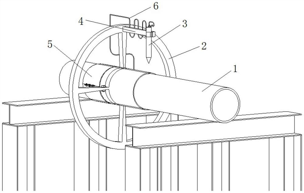
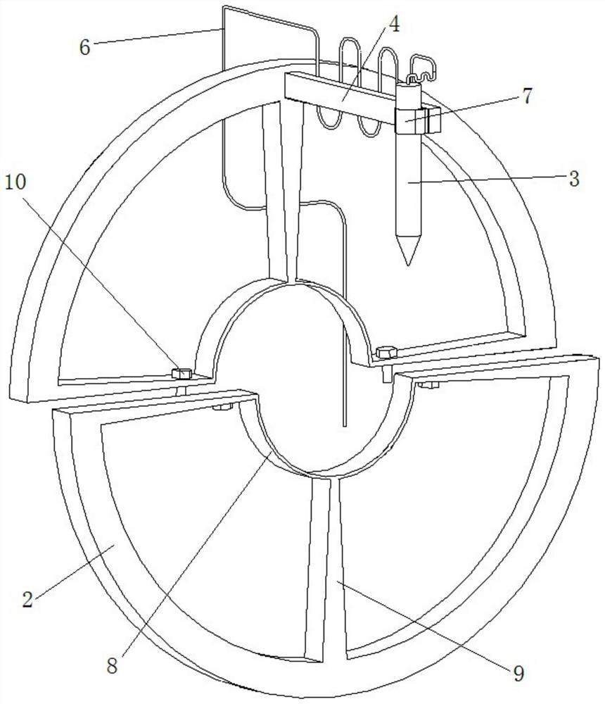
[0028] Such as figure 1 and figure 2 As shown, the present invention provides a steel pipe cutting device, comprising a support frame for horizontal overhead steel pipe 1 and a rotating cutting frame for fixing the cutting machine, the rotating cutting frame includes at least two double-layer frame bodies detachably connected, at least The inner rings 8 of the two double-layer frames are spliced ​​together to form a sleeve for the steel pipe 1 to rotate and ...


PUM


Abstract

,The invention discloses a steel pipe cutting device and method. The steel pipe cutting device comprises a supporting frame used for horizontally erecting a steel pipe in an overhead mode and a rotary cutting frame used for fixing a cutting machine, the rotary cutting frame comprises at least two double-layer frame bodies which are detachably connected the inner rings of the at least two double-layer frame bodies are spliced to form a sleeve opening for rotationally sleeving a steel pipe, the outer rings of the at least two double-layer frame bodies are connected to the outer sides of the inner rings through fixing rods, and one of the outer rings is provided with a fixing base allowing the cutting machine to be installed. The rotary cutting frame is directly arranged on the steel pipe in a sleeving mode to fix the cutting gun, the rotary cutting frame is rotated to cut the steel pipe, and the technical problem that in the prior art, steel pipe cutting is conducted under the complex site working condition and the narrow site is solved. The device is convenient to operate, neat in notch section, high in cutting speed, straight in section, small in size of the rotary cutting frame, convenient to move, suitable for complex environments, low in site requirement and suitable for operation in the complex environments.

Description

technical field [0001] The invention relates to the field of building construction, in particular to a steel pipe cutting device and method. Background technique [0002] In the field of shield tunneling construction, circulating water pipes, sewage pipes, mud pipes, etc. used in shield tunneling construction are generally connected by flanges or hoops. Water pipes and mud pipes have been cycled and used many times, and the flanges or pressure grooves at both ends of the pipeline will be deformed. It is difficult or even impossible to connect the two pipelines. It is necessary to cut off the damaged flanges or pressure grooves at both ends of the pipeline, and re Weld flange or groove. The general cutting method at the construction site is oxyacetylene cutting, which is prone to uneven cutting, and cannot efficiently weld flanges or use a grooving machine to make grooves, and the grooving and welding flanges have high requirements for the flatness of the section cutting, an...

Claims


Application Information

Patent Timeline
Patent Type & Authority Applications(China)
IPC IPC(8): B23K7/00B23K7/10B23K101/06
CPCB23K7/00B23K7/10B23K2101/06
Inventor 陈时光孙尚卿黄天宇陈啸宇骆小芳李海
Owner 中建八局轨道交通建设有限公司
Learn More