
Four-quadrant laser signal detection device

A laser signal and detection device technology, applied in the field of laser signal detection, can solve problems such as loss of effective signal, reduction of effective tracking distance, and increase of detection blind area

Pending Publication Date: 2022-01-21
HEBEI HANGUANG HEAVY IND
View PDF0 Cites 0 Cited by
  • Summary
  • Abstract
  • Description
  • Claims
  • Application Information

AI Technical Summary

Problems solved by technology

During the flight process of the tracker approaching the target from far to near, the energy change of the reflected echo signal is greater than 10 6 times the input range, if the follow-up amplifier circuit adopts fixed gain mode, when the energy of the echo signal is large, the output voltage of the rear end reaches the limit output of the op amp chip, resulting in saturation, which increases the detection blind zone; when the energy of the echo signal is small, it may The effective signal is lost, which reduces the effective tracking distance

Method used


Image

  • Four-quadrant laser signal detection device
  • Four-quadrant laser signal detection device
  • Four-quadrant laser signal detection device

Examples


Embodiment Construction

[0018] The implementation of the present invention will be described in detail below in conjunction with the accompanying drawings and examples, so as to fully understand and implement the process of how to apply technical means to solve technical problems and achieve corresponding technical effects in the present invention. The embodiments of the present application and the various features in the embodiments can be combined with each other under the premise of no conflict, and the formed technical solutions are all within the protection scope of the present invention.

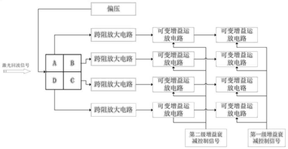
[0019] figure 1 A schematic diagram of a principle of a four-quadrant laser signal detection device according to an embodiment of the present disclosure is shown.

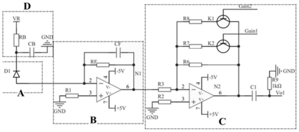
[0020] Such as figure 1 As shown, the device may include: a four-quadrant PIN photodiode, a bias voltage filter circuit, a first-stage transimpedance amplifier circuit and a second-stage variable gain amplifier circuit.

[0021] The four-quadran...


PUM


Abstract

A four-quadrant laser signal detection device comprises a four-quadrant PIN photodiode, a bias voltage filter circuit, a first-stage transimpedance amplification circuit and a second-stage variable gain amplification circuit, wherein the four-quadrant PIN photodiode is used for converting a laser echo signal reflected by a measured target into a photocurrent signal; the output end of the bias voltage circuit is connected with the input end of the four-quadrant PIN photodiode, and the bias voltage circuit is used for adjusting the responsivity of the four-quadrant PIN photodiode; the first-stage transimpedance amplification circuit and the second-stage variable gain amplification circuit form a total amplification circuit which is connected to the output end of the four-quadrant PIN photodiode. According to the detection device, a larger dynamic range can be obtained by adjusting the bias voltage of the PIN photodiode and the gain of the second-stage amplification circuit, the effective tracking distance can be increased, early capture of a target is facilitated, and the blind area distance can be reduced.

Description

technical field [0001] The invention belongs to the technical field of laser signal detection, and in particular relates to a four-quadrant laser signal detection device. Background technique [0002] Laser semi-active detection is the earliest, most mature and widely used guidance technology in laser guidance applications. It uses an independent laser irradiator to irradiate the target object, and realizes target positioning by receiving and using the echo signal diffusely reflected by the target. and tracking. During the flight process of the tracker approaching the target from far to near, the energy change of the reflected echo signal is greater than 10 6 times the input range, if the follow-up amplifier circuit adopts fixed gain mode, when the energy of the echo signal is large, the output voltage of the rear end reaches the limit output of the op amp chip, resulting in saturation, which increases the detection blind zone; when the energy of the echo signal is small, i...

Claims


Application Information

Patent Timeline
IPC IPC(8): G01S17/06G01S17/66G01S7/4861G01S7/489G01S7/4912G01S7/4913
CPCG01S17/06G01S17/66G01S7/4861G01S7/489G01S7/4913G01S7/4918
Inventor 赵婷婷孟凡强吴长安曹帅帅
Owner HEBEI HANGUANG HEAVY IND
Learn More