
Welding system for aluminum alloy laser welding and surface treatment method

A laser welding and welding system technology, applied in laser welding equipment, welding equipment, metal processing equipment, etc., to achieve the effect of simple and easy-to-operate surface treatment method, good welding quality, and improved welding quality

Pending Publication Date: 2022-01-11
HWI-NICHST WELDING & ENG INNOVATION CENT (QINGDAO) CO LTD
View PDF9 Cites 2 Cited by
  • Summary
  • Abstract
  • Description
  • Claims
  • Application Information

AI Technical Summary

Problems solved by technology

[0003] The purpose of the present invention is to provide a welding system and a surface treatment method for aluminum alloy laser welding to solve the existing technical problems in the above-mentioned background technology

Method used


Image

  • Welding system for aluminum alloy laser welding and surface treatment method
  • Welding system for aluminum alloy laser welding and surface treatment method
  • Welding system for aluminum alloy laser welding and surface treatment method

Examples


Embodiment 1

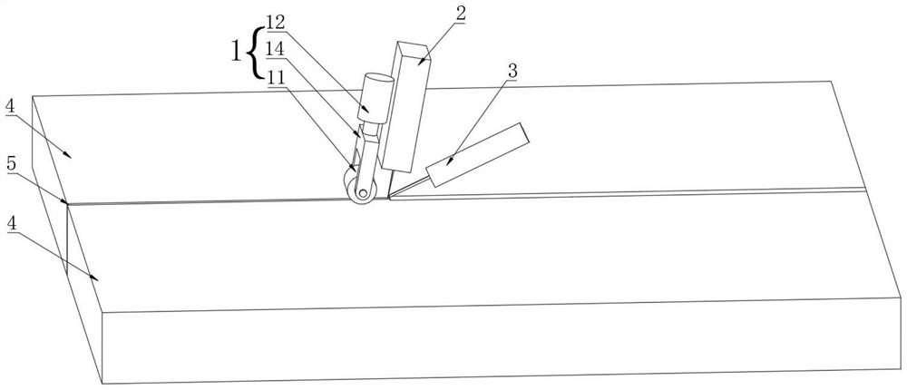
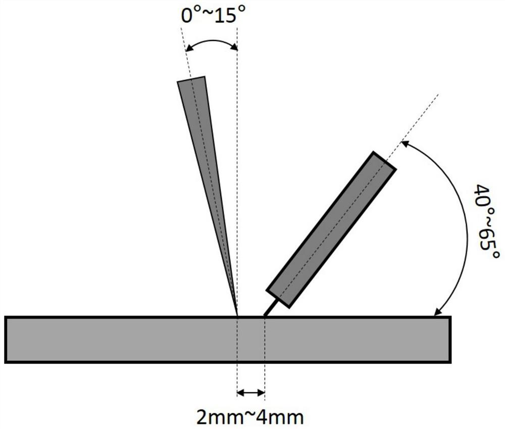
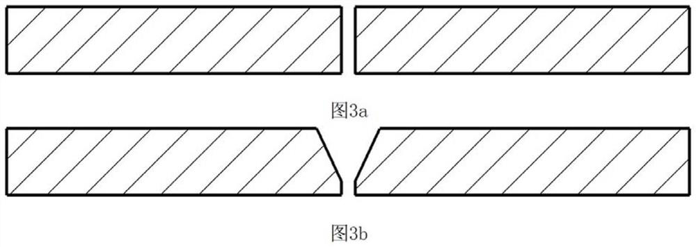
[0034] On the one hand, if Figure 1 to Figure 4 As shown, the present invention provides a welding system for aluminum alloy laser welding, including a workbench, a surface processing device 1, a laser welding device 2 and an arc welding device 3, the workbench is used to fix the parts to be welded 4 and A weld seam 5 is reserved between the parts to be welded 4, the surface processing device 1 includes a roller 11 and a hydraulic control mechanism 12, the roller 11 abuts on the parts to be welded 4 and is located at the top of the weld seam 5, the The output end of the hydraulic control mechanism 12 is arranged on the top of the roller 11, the outer surface of the roller 11 is provided with a hard particle layer 13, and the laser welding device 2 and the arc welding device 3 are successively arranged on the surface along the direction opposite to the welding direction. One side of the processing device 1. It should be noted that the hydraulic control mechanism 12 is arrange...

Embodiment 2

[0047] On the basis of the above technical solutions, if Figure 5 As shown, it also includes a blowing device 6 for removing metal debris. The blowing device 6 includes an air source and a nozzle 61. One end of the nozzle 61 is connected to the air source, and the other end is correspondingly arranged on the roller 11 and the laser welding device 2. Between; the metal debris produced by the rollers to be welded can be cleaned in time to prevent welding defects such as impurities. Specifically, the gas source (not shown) on the blowing device 6 and the laser welding device 2 can share a set of shielding gas supply system, the shielding gas gas adopts the combination inert gas of argon and helium, the The nozzle 61 is correspondingly arranged on one side of the position between the roller 11 and the laser welding device 1 , and blows off the metal debris that may be produced on the surface of the part 4 to be welded after being rolled by the roller 11 from the side.

[0048] O...

Embodiment 3

[0050] On the basis of the above-mentioned technical solution, a vibrator (not shown in the figure) is also included, and the vibrator is arranged on the hydraulic control mechanism 12; its vibration direction is parallel to the direction in which the hydraulic control mechanism 12 applies pressure to the rollers to vibrate up and down , the vibration direction is as Figure 5 As shown by the middle arrow, the pressure of the roller 11 on the part 4 to be welded can be increased, which is beneficial to the damage of the oxide film on the surface of the aluminum alloy, increases the surface roughness of the part 4 to be welded, facilitates subsequent welding operations, and has good welding quality. Specifically, the vibrator adopts a hydraulic vibration motor, which can be obtained from the prior art, and will not be repeated here.

[0051] On the other hand, the surface treatment method for aluminum alloy laser welding in this embodiment is basically the same as that in Embod...


PUM


Abstract

The invention relates to the technical field of welding, in particular to a welding system for aluminum alloy laser welding. The welding system comprises a workbench, a surface machining device, a laser welding device and an electric arc welding device. A hard particle layer on a roller in the surface machining device is used for damaging a surface oxidation film of an aluminum alloy, so that the surface roughness of the aluminum alloy is improved, the reflection effect of the surface of the aluminum alloy on laser is effectively reduced, the welding process of the aluminum alloy is stabilized, and attractive and defect-free welding seams are obtained. Meanwhile, the invention further provides a surface treatment method of a to-be-welded part of the aluminum alloy by using the laser welding system, and a traditional surface treatment method used for laser or laser-arc welding hybrid welding of the aluminum alloy is changed, so that real-time treatment, namely surface treatment and the welding process of the surface of the be-welded part in the aluminum alloy welding process can be conducted synchronously, repeated treatment caused by the fact that the interval between surface pretreatment and the welding process is too long is avoided, the surface treatment method is simple and easy to operate, the welding pretreatment process is reduced, and the welding quality is improved.

Description

technical field [0001] The invention relates to the field of welding technology, in particular to a welding system and a surface treatment method for aluminum alloy laser welding. Background technique [0002] With the emergence and continuous development of high-power lasers, laser and laser arc hybrid welding technology has been greatly developed in the field of aluminum alloy welding. Due to the high thermal conductivity, low ionization energy and laser reflection of aluminum alloys, the welding process of aluminum alloys is very unstable, which eventually leads to problems such as poor weld formation, large fluctuations in penetration depth, and high weld porosity. , so surface treatment must be performed when laser welding aluminum alloys. The surface treatment methods of aluminum alloys before welding are divided into mechanical methods, chemical methods and laser treatment methods; mechanical methods mainly include grinding, shot peening and sandblasting, etc., which...

Claims


Application Information

Patent Timeline
Patent Type & Authority Applications(China)
IPC IPC(8): B23K26/00B23K26/346B23K26/348B23K26/70
CPCB23K26/346B23K26/348B23K26/0093B23K26/702Y02P70/10
Inventor 李康宁徐良杨海锋崔辉马天宇张崇放鞠静静于洪军
Owner HWI-NICHST WELDING & ENG INNOVATION CENT (QINGDAO) CO LTD
Learn More