


Quick Research
Generate reliable direction feasibility study reports for your R&D in just a few steps.

Technical Q&A
Discover and master advanced knowledge NOW. Basics, ideas, possibilities, all at once.

Find Solutions
As an expert in R&D theories, this can generate solutions to your technical problems instantly.

Evaluate Feasibility
Analyze your overall solution with one click, know your potential R&D risks in advance.

Monitor Landscape
Get weekly tech updates, stay abreast of the latest tech innovations and key insights.
Low-carbon emission type VOCs purification device and method adopting low-temperature plasma technology
A low-temperature plasma and purification device technology, applied in separation methods, chemical instruments and methods, membrane technology, etc., to achieve the effects of strong adaptability to working conditions, reduced footprint, and compact equipment structure
- Summary
- Abstract
- Description
- Claims
- Application Information
AI Technical Summary
Problems solved by technology
Method used
Image

Examples
Embodiment 1
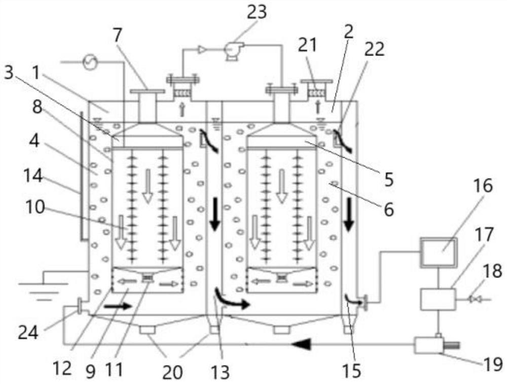
[0028] Such as figure 1 Shown is a schematic diagram of the device structure of the present invention, a low-carbon emission type VOCs purification device of low-temperature plasma technology, including: gas-liquid phase purification unit one 1, gas-liquid phase purification unit two 2, the gas-liquid phase purification unit two The gas outlet of phase purification unit one 1 is connected with the inlet port of said gas-liquid phase purification unit two 2; said gas-liquid phase purification unit one 1 includes: gas phase VOCs purification chamber one 3 and liquid phase carbon capture Chamber one 4, the gas phase VOCs purification chamber one 3 is placed inside the liquid phase carbon capture chamber one 4; the gas-liquid phase purification unit two 2 includes: gas phase VOCs purification chamber two 5 and liquid phase carbon capture Collection chamber two 6, the gas-phase VOCs purification chamber two 5 is placed inside the liquid-phase carbon collection chamber two 6, the li...
Embodiment 2
[0037] This embodiment provides a low-carbon emission type VOCs purification method of low-temperature plasma technology. VOCs waste gas enters the gas-phase VOCs purification chamber-3 of the gas-liquid phase purification unit-1 through the air inlet 7, and the low-temperature The high-energy electrons generated by the plasma discharge react with the active groups and are transformed into small molecular inorganic substances such as carbon dioxide and water, as well as a small amount of by-products. The purified tail gas enters in the form of microbubbles after gas phase equalization and micropore diffusion. In the liquid-phase carbon capture chamber-4, the carbon dioxide in the tail gas is absorbed by the absorption solution, and the remaining tail gas is collected at the top outlet of the gas-liquid phase purification unit-1, and the gas is intercepted by the demister 21 After carrying the droplets, the booster air pump 23 sends them into the gas-liquid phase purification un...
PUM
 Abstract
Description
Claims
Application Information
 - R&D Engineer
- R&D Manager
- IP Professional
- Industry Leading Data Capabilities
- Powerful AI technology
- Patent DNA Extraction
Browse by: Latest US Patents, China's latest patents, Technical Efficacy Thesaurus, Application Domain, Technology Topic, Popular Technical Reports.
© 2024 PatSnap. All rights reserved.Legal|Privacy policy|Modern Slavery Act Transparency Statement|Sitemap|About US| Contact US: help@patsnap.com