
Polyhedral groove grease coating equipment

A technology of polyhedron and grease, which is applied to the device and coating of the surface coating liquid, can solve the problems of low work efficiency, narrow and deep polyhedral groove space, and narrow operating space, so as to achieve simple, compact and safe equipment structure Reliable semi-automatic, solve the effect of narrow operating space

Active Publication Date: 2020-03-27
BEIJING UNIV OF TECH
View PDF6 Cites 2 Cited by
  • Summary
  • Abstract
  • Description
  • Claims
  • Application Information

AI Technical Summary

Problems solved by technology

[0002] There are the following important limiting factors in solving the automatic grease coating process of polyhedral grooves in narrow and deep spaces. First, there are flammable and explosive materials in the cylinder, and avoiding the generation of electricity and sparks is an important factor; second, polyhedral grooves The space where the groove is located is narrow and deep, and the designated surface to be coated with grease is complex
The current solution is to manually apply grease to the polyhedral groove. In the process of manually applying grease, on the one hand, the staff needs to enter a narrow and deep space to work, and the operating space is narrow and inconvenient to operate. On the other hand, the operator Difficult to apply a uniform thickness of grease and can easily cause damage to the product
The method of manually applying grease is difficult to operate, which makes the staff physically tired, low work efficiency, and the effect of applying grease is not good

Method used


Image

  • Polyhedral groove grease coating equipment
  • Polyhedral groove grease coating equipment
  • Polyhedral groove grease coating equipment

Examples


Embodiment Construction

[0033] The present invention will be further described below in conjunction with the accompanying drawings and embodiments.

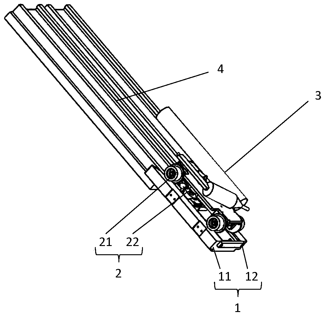
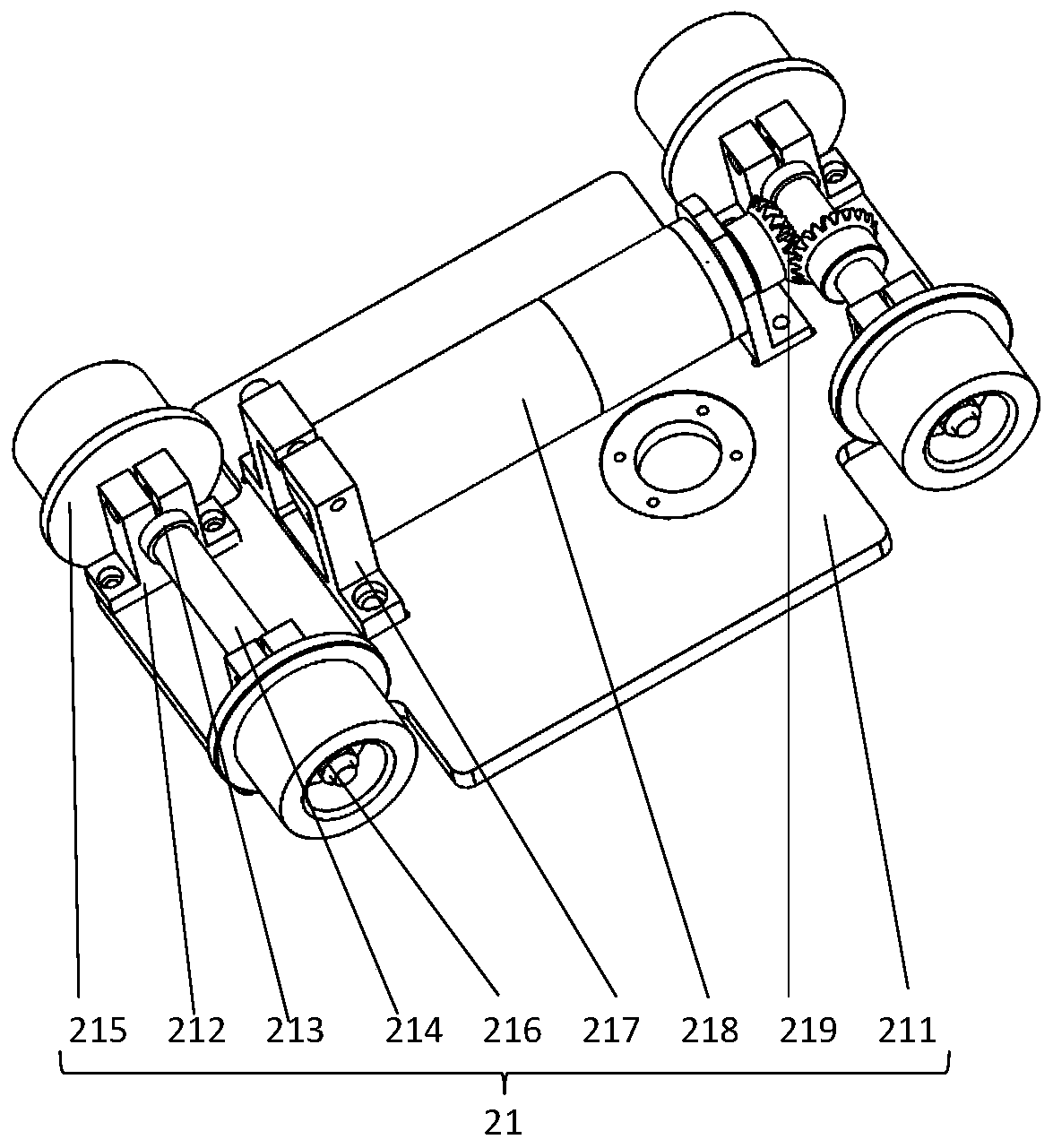
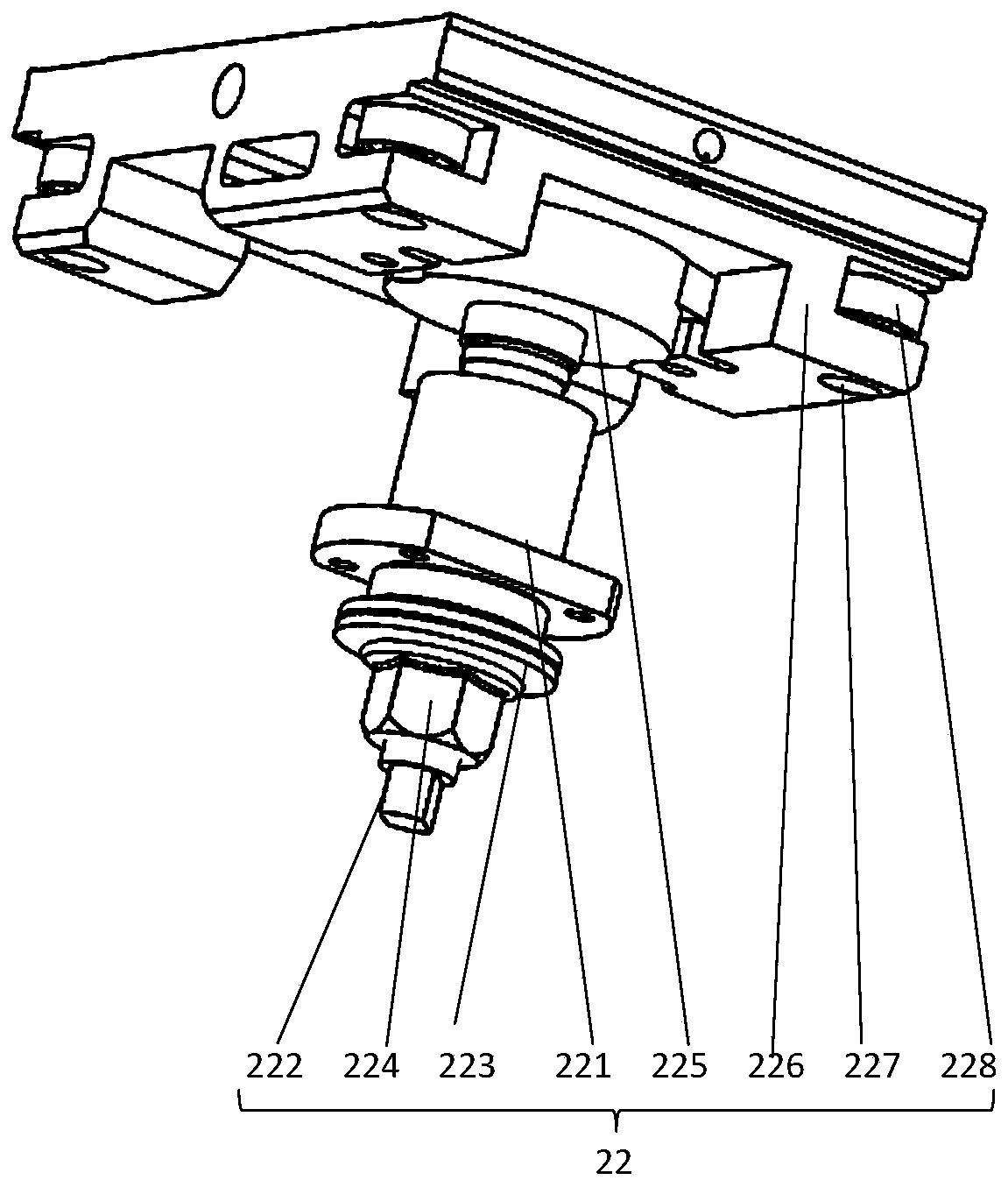
[0034] Also refer to figure 1 , figure 2 , image 3 , Figure 4 , Figure 5 , Image 6 , Figure 7 , Figure 8 , Figure 9 , Figure 10 , Figure 11 , Figure 12 , Figure 13 , Figure 14 ,in, figure 1 It is a schematic diagram of the overall structure of the polyhedral groove coating grease equipment of the present invention; figure 2 for figure 1 A schematic diagram of the internal structure of the power trolley assembly 21 of the oiling mechanism assembly 2 of the polyhedral groove coating grease equipment shown; image 3 for figure 1 A schematic diagram of the internal structure of the single-axis transmission oiling assembly 22 of the oiling mechanism assembly 2 of the polyhedral groove coating grease equipment shown; Figure 4 for image 3 The axonometric schematic diagram of the greased slider 226 of the single shaft transmiss...


PUM


Abstract

The invention provides polyhedral groove grease coating equipment and relates to the field of special elevator guide rails. The polyhedral groove grease coating equipment comprises a butting assembly,an oiling mechanism assembly and a pneumatic oiling machine. The oiling mechanism assembly comprises a power trolley assembly and a single-shaft transmission oiling assembly. The single-shaft transmission oiling assembly comprises a linear bearing B, a stepped shaft B, a butterfly spring, a locknut B, a self-aligning bearing and bearing block, oiling sliding blocks, butting screws and micro bearings. The deformation of the butterfly spring is changed by adjusting the locknut B. The polyhedral groove grease coating equipment is simple and compact in structure and convenient to operate. The problems that the operation space is narrow and small, and the labor intensity is large through manual grease coating are solved. The polyhedral groove grease coating equipment is low in cost and realizes safe and reliable semi-automation. Meanwhile, the problem of working limitation of flammable and combustible articles is solved through pneumatic drive, and the polyhedral groove grease coating equipment realizes equal-thickness grease coating on cylinders and polyhedrons to be coated with grease, greatly reduces the working intensity of working staff, thereby improving the grease coating efficiency and quality.

Description

technical field [0001] The invention relates to the technical field of special elevator guide rails, in particular to a polyhedral groove coating grease equipment. Background technique [0002] There are the following important limiting factors in solving the automatic grease coating process of polyhedral grooves in narrow and deep spaces. First, there are flammable and explosive materials in the cylinder, and avoiding the generation of electricity and sparks is an important factor; second, polyhedral grooves The space where the groove is located is narrow and deep, and the designated surface to be coated with grease is complex. The current solution is to manually apply grease to the polyhedral groove. In the process of manually applying grease, on the one hand, the staff needs to enter a narrow and deep space to work, and the operating space is narrow and inconvenient to operate. On the other hand, the operator It is difficult to apply grease with an even thickness, and it...

Claims


Application Information

Patent Timeline
IPC IPC(8): B05C5/02
CPCB05C5/0275
Inventor 许东来卢超伟孙国芹李岩张文杰李明飞张宏图
Owner BEIJING UNIV OF TECH
Learn More