
Laser diode

A laser diode and tube cap technology, applied in the laser field, can solve the problems of affecting the quality of the spot, large beam loss, and small divergence angle, etc., and achieve the effects of high conversion efficiency, high collimation, and small radius of curvature

Pending Publication Date: 2021-11-12
SHANXI OVISION OPTRONICS CO LTD
View PDF0 Cites 0 Cited by
  • Summary
  • Abstract
  • Description
  • Claims
  • Application Information

AI Technical Summary

Problems solved by technology

However, during the collimation process of the output beam in the fast axis direction, the output beam is not 100% completely permeable through each lens, that is, there will be beam loss when the output beam passes through each lens, so the more lenses that pass through, the more the beam loss will be. will be larger, resulting in poor quality of the final spot; at the same time, because the output beam will produce spherical aberration and coma when it is repeatedly refracted and reflected by the lens, which will seriously affect the quality of the final spot, so how to design a A laser diode that can not only guarantee a certain spot quality, but also realize a smaller divergence angle in the fast axis direction of the output beam is a key problem that needs to be solved at present.

Method used


Image

  • Laser diode
  • Laser diode
  • Laser diode

Examples


Embodiment Construction

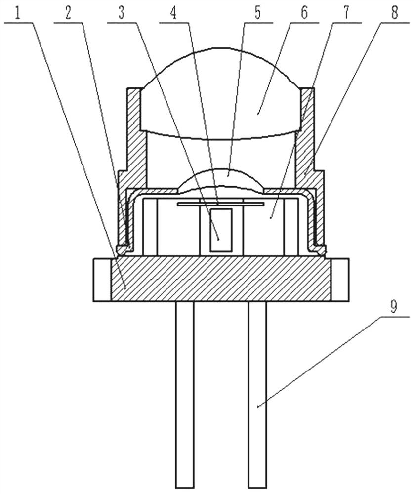
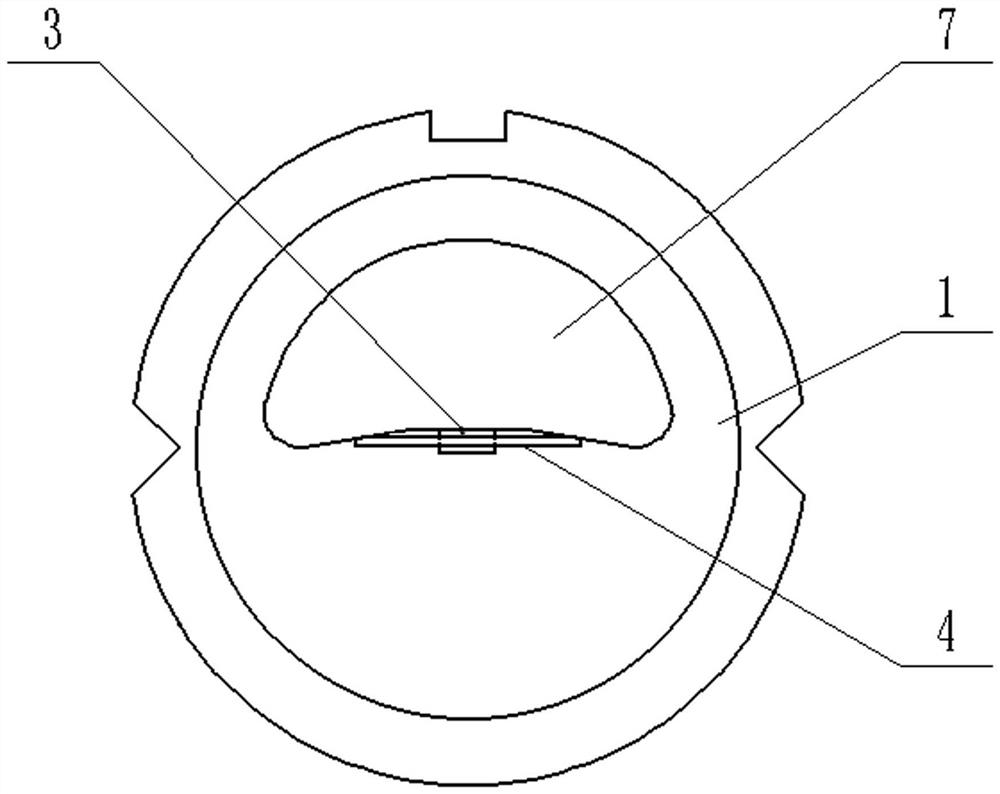
[0011] Such as figure 1 with figure 2 A laser diode, comprising a tube base 1, a tube cap 2, a chip 3 and a radiator 7 for dissipating heat to the chip 3, the tube cap 2 is provided with a hole, and a light-transmitting mirror is fixedly installed in the hole, and also includes a tube fixedly installed on the Inside the tube cap 2 (it is well known to those skilled in the art that if it is fixedly installed in the tube cap 2, the two ends of the bare fiber 4 can be directly or indirectly fixed to the heat sink 7 to achieve fixed installation) and located between the chip 3 and the light-transmitting mirror Bare fiber 4 (the optical fiber has a core, cladding, and coating layer from the inside to the outside in sequence. Those skilled in the art know that the bare fiber 4 is an optical fiber with the coating removed), the axial direction of the bare fiber 4 and the light emission of the chip 3 The direction is vertical, and the light-transmitting mirror is a meniscus-shaped ...


PUM

PropertyMeasurementUnit
Diameteraaaaaaaaaa

Abstract

The invention relates to the technical field of laser, in particular to a laser diode. The invention aims to provide the laser diode which not only can ensure certain light spot quality, but also can reduce the divergence angle of a light beam in the fast axis direction, the laser diode comprises a tube seat, a tube cap, a chip and a radiator used for radiating heat of the chip, a hole is formed in the tube cap, and a light-transmitting mirror is fixedly mounted in the hole. The laser diode also comprises a bare fiber which is fixedly installed in the tube cap and located between the chip and the light-transmitting mirror, the axial direction of the bare fiber is perpendicular to the light-emitting direction of the chip, the light-transmitting mirror is a meniscus spherical lens with the concave direction being the light-emitting direction of the chip, and the meniscus spherical lens corresponds to the bare fiber in position, so that a clear lens set is formed. A first gap is arranged between the bare fiber and the chip, so that the light-emitting point of the chip and the clear point of the clear lens set are located at the same point. The laser diode has the advantages of being simple in structure, high in light beam collimation degree and good in light spot effect.

Description

technical field [0001] The invention relates to the technical field of lasers, in particular to a laser diode. Background technique [0002] With the continuous improvement of the collimation of the output beam of laser diodes in recent years, laser diodes have been widely used in processing, production, medical treatment and other fields. The existing laser diode includes a tube base 1, a tube cap 2, a chip 3, a heat sink 7, a lens barrel 8, and pins 9, and the tube cap 2 is vertically fixed on the upper surface of the tube base 1 and formed with the upper surface of the tube base 1. A cavity, the cavity is provided with a chip 3 and a heat sink 7 for dissipating heat from the chip 3, the lens barrel 8 is sleeved on the outer wall of the tube cap 2 and the lens barrel 8 protrudes from the tube cap in a direction away from the tube base 1 2, and form the overhanging part of lens barrel 8, the cap top of cap 2 is provided with hole, and the light-transmitting mirror is fixed...

Claims


Application Information

Patent Timeline
IPC IPC(8): H01S5/02251H01S5/02253
CPCH01S5/02251H01S5/02253
Inventor 陈海洋胡元元王园兰旭阳
Owner SHANXI OVISION OPTRONICS CO LTD
Learn More