
A drying device for ceramic blanks

A drying device, a technology made of ceramics, applied in the direction of ceramic products drying, drying, drying machine, etc., can solve the problems of complex conveyor belt or chain transmission structure, high operation and maintenance costs, long transmission distance, etc., to achieve the green body Good drying effect, compact structure, and reduced floor space

Active Publication Date: 2022-08-09
醴陵市新创奕自动化设备有限公司
View PDF10 Cites 0 Cited by
  • Summary
  • Abstract
  • Description
  • Claims
  • Application Information

AI Technical Summary

Problems solved by technology

At present, the known drying devices for daily-use ceramic blanks are all set to a longer length according to the assembly line to ensure the drying time and effect. The green body forming and drying conveying process in the gypsum molding mold is basically divided into two transmission methods. One is that the conveyor belt linear transmission device is arranged in single row, double row or more than multiple rows, and a conversion device is arranged between each row, and the other is a long-distance transmission device using a sprocket chain elliptical disc. Either way is presented A single layer is arranged on the ground, resulting in a large footprint, long transmission distance, complex conveyor belt or chain transmission structure, poor stability, high post-operation and maintenance costs, and the bottom of the gypsum molding mold cannot be heated, and local humidity affects the drying effect

Method used


Image

  • A drying device for ceramic blanks
  • A drying device for ceramic blanks
  • A drying device for ceramic blanks

Examples


Embodiment Construction

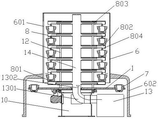
[0021] See figure 1 ——5, the drying device for ceramic blanks provided by the present invention includes a disc worktable 1 driven by a power device to rotate intermittently, and the diameter of the disc worktable 1 is smaller than that of the disc. Table 1 and the 6-layer heating plate 8 (usually 2 to 8 layers of drying plates 8) that rotates with the disk table 1 is fixed relative to the disk table 1 and is arranged on the disk table 1 to The outer shell 6 covered by the heating plate 8, and the heating device 13 that provides hot air into the outer shell 6; The hot air main pipe 14 is provided, and the heating plate 8 is provided with a hot air chamber that communicates with the hot air main pipe 14; except for the heating plate 8 of the lowermost layer, the bottom of the other heating plates 8 is provided with a hot air outlet 804 that communicates with the hot air chamber. The side of the outer shell 6 is provided with a plaster mold exchange port 601 corresponding to th...


PUM

PropertyMeasurementUnit
diameteraaaaaaaaaa

Abstract

The invention discloses a drying device for ceramic blanks, comprising a disc worktable which is driven by a power device to rotate intermittently, a disc worktable which is arranged on the disc worktable with a diameter smaller than the disc worktable, The heating plate that rotates on the disc worktable, the casing that is fixed relative to the disc worktable and is provided on the disc worktable to cover the heating disc, and the heating device that provides hot air into the casing; The central part of the disc worktable is fixedly provided with a hot air main pipe that communicates with the heating device and is arranged vertically, and the heating plate is provided with a hot air chamber that communicates with the hot air main pipe; The bottom of the heating plate is provided with a hot air port communicating with the hot air chamber; the side surface of the casing is provided with plaster mold exchange ports corresponding to the heating plates of each layer. The invention has the advantages of small footprint, compact and simple structure, stable production, high efficiency and good drying effect of the green body.

Description

technical field [0001] The invention belongs to ceramic production equipment, and in particular relates to a drying device for making ceramic blanks. Background technique [0002] Ceramics are widely used as a kind of living utensils. The production process includes the use of clay viscous materials, and the processes of batching, molding, drying, and roasting are fired to form. At present, the known drying devices for making ceramic blanks for daily use are all set with a longer length according to the assembly line to ensure drying time and effect. , one is that the conveyor belt linear transmission device is arranged in single row, double row or more than one row, and a conversion device is arranged between each row, and the other is a long-distance transmission device using a sprocket chain elliptical disk, no matter which method is used. The single layer is arranged on the ground, resulting in large floor space, long transmission distance, complex conveyor belt or chai...

Claims


Application Information

Patent Timeline
Patent Type & Authority Patents(China)
IPC IPC(8): F26B11/18F26B21/00F26B25/00B28B3/12B28B11/24
CPCF26B11/18F26B21/001F26B21/004F26B25/003B28B3/12B28B11/243F26B2210/02Y02P40/60
Inventor 邹湘科
Owner 醴陵市新创奕自动化设备有限公司
Learn More