UASB reactor system with self-heating function
A reactor system and reactor technology, applied in chemical instruments and methods, water treatment parameter control, water/sludge/sewage treatment, etc., can solve problems such as reduced treatment efficiency, changes in living environment, and destruction of anaerobic environment , to achieve the effect of good heat preservation effect and good purification effect
- Summary
- Abstract
- Description
- Claims
- Application Information
AI Technical Summary
Problems solved by technology
Method used
Image
Examples
Embodiment 1
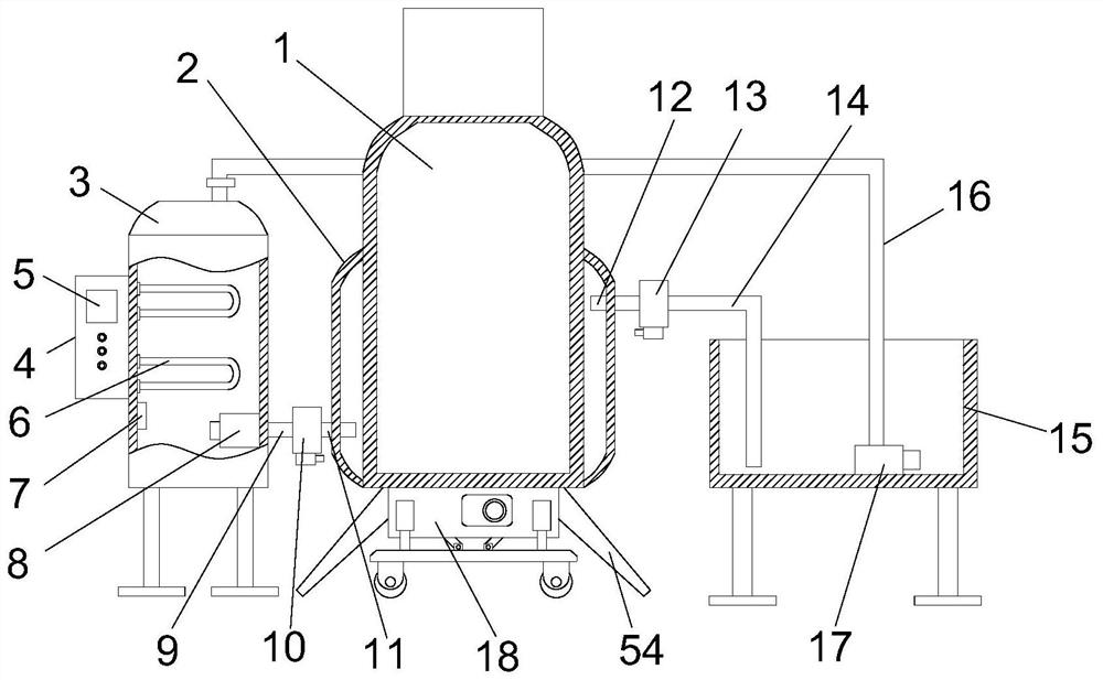
[0032] refer to Figure 1-7 , a UASB reactor system with self-heating function, including a UASB reactor body 1, a hot water jacket 2, an electric heating tank 3 and a cold water collection tank 15, and the hot water jacket 2 is fixedly wrapped on the UASB reactor body 1 Outside, the electric heating tank 3 and the cold water collection tank 15 are respectively located on both sides of the UASB reactor body 1, the bottom end of the UASB reactor body 1 is fixedly connected with a support leg 54, and the UASB reactor body 1 and the hot water jacket 2 are connected. It is connected by a hot water conduction mechanism, a cold water conduction mechanism is communicated between the hot water jacket 2 and the cold water collection tank 15, and a return water pipe 16 is also provided between the electric heating tank 3 and the cold water collection tank 15, and one end of the return water pipe 16 is connected to the cold water collection tank 15. The top of the electric heating tank 3...
Embodiment 2
[0034] refer to Figure 1-7 The difference between this embodiment and Embodiment 1 is that the hot water conduction mechanism includes a hot water inlet pipe A9, a hot water inlet pipe B11 and a first water flow regulating mechanism 10, and the hot water inlet pipe A9 is connected to the electric heating tank 3 near the UASB reaction On one side of the boiler body 1, the hot water inlet pipe B11 is connected to the side of the hot water jacket 2 close to the electric heating tank 3, one end of the hot water inlet pipe B11 extends into the hot water jacket 2, and the hot water inlet pipe B11 The other end is fixedly connected with the first water flow regulating mechanism 10, one end of the hot water inlet pipe A9 extends into the electric heating tank 3 and is connected with the second water pump 8, and the other end of the hot water inlet pipe A9 is connected to the first water flow regulating mechanism 10. After disassembling and connecting, the hot water in the electric he...
Embodiment 3
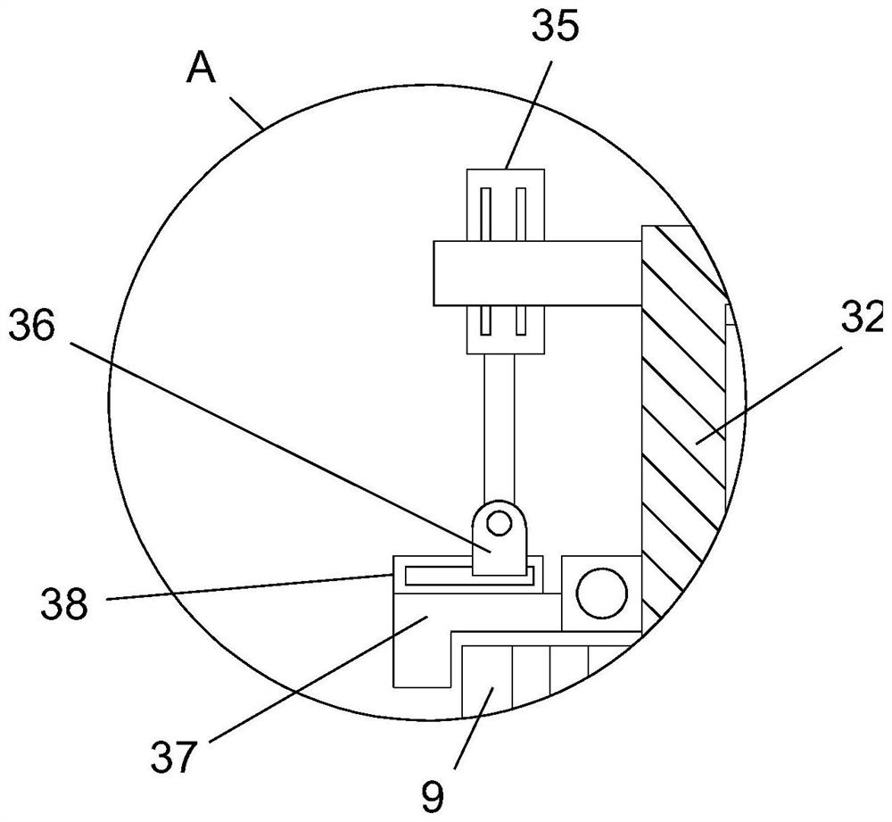
[0037] refer to Figure 1-7 , the difference between this embodiment and Embodiment 1 is that the first water flow adjustment mechanism 10 and the second water flow adjustment mechanism 13 include a casing 32, the casing 32 is provided with a first installation cavity 39, and the casing 32 is located in the first installation cavity 32. A second installation cavity 40 is provided above and below the cavity 39. One end of the hot water inlet pipe B11 and the cold water discharge pipe B14 extends into the second installation cavity 40. The two second installation cavities 40 are respectively rotatably installed with the first installation cavity 40. The threaded rod 43 and the second threaded rod 49, a connecting rod 44 is rotatably installed in the first installation cavity 39, the top end of the connecting rod 44 is fixedly connected with the second threaded rod 49, and the bottom end of the connecting rod 44 is connected with the first threaded rod 43 , the outer sides of the...
PUM
 Abstract
Description
Claims
Application Information
 - R&D
- Intellectual Property
- Life Sciences
- Materials
- Tech Scout
- Unparalleled Data Quality
- Higher Quality Content
- 60% Fewer Hallucinations
Browse by: Latest US Patents, China's latest patents, Technical Efficacy Thesaurus, Application Domain, Technology Topic, Popular Technical Reports.
© 2025 PatSnap. All rights reserved.Legal|Privacy policy|Modern Slavery Act Transparency Statement|Sitemap|About US| Contact US: help@patsnap.com


