Eureka AIR delivers breakthrough ideas for toughest innovation challenges, trusted by R&D personnel around the world.

Forming and detecting integrated equipment used for high-end equipment manufacturing

A kind of equipment and high-end technology, applied in the direction of manufacturing tools, metal processing equipment, grinding/polishing equipment, etc., can solve problems such as burrs and convex edges on the edge of the shell, affecting size detection, etc., to speed up molding speed, facilitate recycling, Effect of preventing debris splashing

Active Publication Date: 2021-10-15
管艳芳
View PDF6 Cites 1 Cited by
  • Summary
  • Abstract
  • Description
  • Claims
  • Application Information

AI Technical Summary

Problems solved by technology

[0004] Aiming at the deficiencies of the existing technology, the present invention provides a high-end equipment manufacturing integrated forming and testing equipment, which solves the problem of the existing injection molds used in the production of high-end equipment proposed in the above-mentioned background technology, for example: used in the production of engine casings The injection mold is mainly composed of an upper mold and a lower mold. After assembly, there will inevitably be gaps between the two, which will cause burrs and convex edges on the edges of the high-end equipment after molding, especially for the shell. The shell formed by injection molding The body is divided into two parts and then assembled to form a whole. The gap between the upper mold and the lower mold will cause serious burrs and convex edges on the edge of the molded shell, which will easily affect the subsequent size inspection.

Method used


Image

  • Forming and detecting integrated equipment used for high-end equipment manufacturing
  • Forming and detecting integrated equipment used for high-end equipment manufacturing
  • Forming and detecting integrated equipment used for high-end equipment manufacturing

Examples


Embodiment Construction

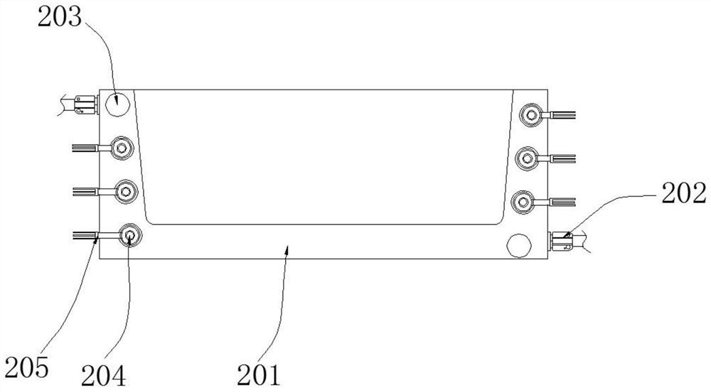
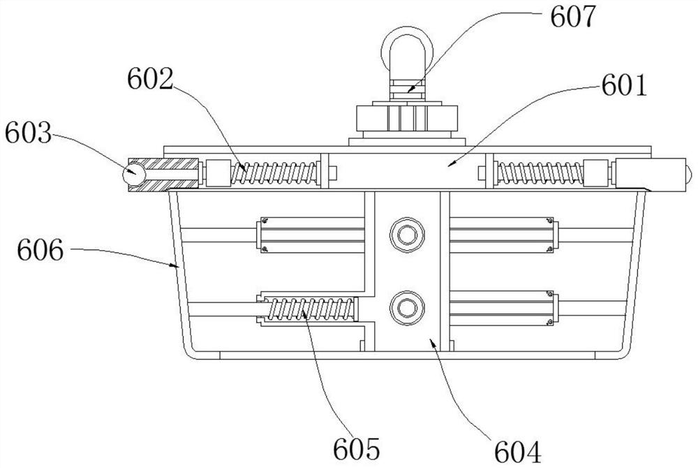
[0028] see Figure 1 to Figure 5 , the present invention provides a technical solution: an integrated forming and testing equipment for high-end equipment manufacturing, including a working base 1 and an upper mold assembly 6, a lower mold assembly 2 is provided on the left side of the surface of the operating base 1, and the lower mold assembly A slide rail 3 is arranged on the top of the part 2, and a sliding push rod 4 is arranged inside the slide rail 3, and a drive motor 5 is connected to the bottom of the slide push rod 4, and the upper die assembly 6 is arranged on the bottom of the drive motor 5. Component 6 includes mold cover 601, spring hollow rod 602, friction ball 603, cavity bottom template 604, spring rod 605, side template 606 and water supply pipe 607, the inner side of mold cover 601 is provided with spring hollow rod 602, and spring The outer end of the empty rod 602 is embedded with a friction ball 603, the bottom of the mold cover 601 is connected with a c...


PUM


Abstract

The invention discloses forming and detecting integrated equipment used for high-end equipment manufacturing, and relates to the technical field of equipment manufacturing. The forming and detecting integrated equipment used for high-end equipment manufacturing specifically comprises an operation bottom plate and an upper mold assembly, wherein a lower mold assembly is arranged at the left side of the surface of the operation bottom plate, sliding push rods are arranged in a sliding rail, the upper mold assembly is arranged at the bottom of a driving motor, the bottom of a mold cover is connected with a cavity bottom mold plate, a side mold plate is fixed to the outer side of a spring rod, the top of the mold cover is connected with a water supply pipe, and laser contour projection equipment is arranged at the middle portion of the operation bottom plate. According to the forming and detecting integrated equipment used for high-end equipment manufacturing, burrs on the side faces of the edges of a metal material are polished and eliminated after injection molding and compression molding of the metal material, the polishing degree is limited, thus the burrs are completely eliminated, meanwhile, the situation that the size of a shell is affected by excessive polishing is avoided, and metal scraps generated by polishing are magnetically adsorbed and collected so that the scraps can be prevented from sputtering, and meanwhile, the scraps can be conveniently recycled in the later period.

Description

technical field [0001] The invention relates to the technical field of high-end equipment manufacturing, in particular to a forming and testing integrated equipment for high-end equipment manufacturing. Background technique [0002] High-end equipment refers to product components with high technical content, which are at the high end of the value chain and occupy the core part of the industrial chain, such as: the engine on the car, the motor on the cutting machine, and the host computer in the computer. For precision reasons, it is necessary to install precision parts in a special housing to ensure that the safety will not be affected. At present, part of the housing of high-end equipment is formed by injection molding. [0003] Existing injection molds used in the production of high-end equipment, such as: the injection mold used in the production of engine casings are mainly composed of upper mold and lower mold, and there will inevitably be gaps between the two after ass...

Claims


Application Information

Patent Timeline
Patent Type & Authority Applications(China)
IPC IPC(8): B22D18/02B22D27/04B22D31/00B24B9/04B24B55/02B24B55/06G01B11/24
CPCB22D18/02B22D27/04B22D31/00B24B9/04B24B55/06B24B55/02G01B11/2433
Inventor 管艳芳
Owner 管艳芳
Why Eureka
Eureka Blog
Learn More